
Metastability Interstitial High Entropy Alloy Design
J. Su, X. Wu, D. Raabe, Z. Li, "Deformation-driven bidirectional transformation promotes bulk nanostructure formation in a metastable interstitial high entropy alloy", Acta Materialia 167 (2019) 23–39. Max-Planck-Institut, Düsseldorf, Germany.
Design concept
High entropy alloys (HEAs) built on multiple principal elements open a large compositional space in which phase stability, stacking fault energy, and therefore deformation behavior can be tuned deliberately. The alloy studied here is a non-equiatomic, carbon-doped interstitial high entropy alloy (iHEA): 49.5Fe-30Mn-10Co-10Cr-0.5C (at. %). Its FCC austenitic phase is positioned close to the thermodynamic stability limit of the HCP phase, and the whole design rests on this proximity.
The idea is that under mechanical load the alloy undergoes sequential athermal forward (FCC to HCP martensite) and reverse (HCP to FCC) transformations, a bidirectional transformation effect (Bi-TRIP). The repeated transformations and the accompanying partial dislocation activity build a bulk nanostructure of nano-lamellae, nano-subgrains, and nano-twins. A short temper at 400 °C then restores a single FCC phase while keeping the nanoscale features in place. The best variant, the 34 % cold rolled and tempered condition, combines an ultimate tensile strength of 1.05 GPa with 35 % total elongation: a strength–ductility combination that is rarely seen in bulk nanostructured alloys.
Material and processing
The starting material is the non-equiatomic interstitial HEA with nominal composition 49.5Fe-30Mn-10Co-10Cr-0.5C (at. %). The as-cast alloy is hot rolled at 900 °C to a 50 % thickness reduction, homogenized at 1200 °C for 2 h in an Ar atmosphere, and water quenched. After this treatment the alloy consists of a single FCC phase with equiaxed grains of about 65 µm average size. The cold rolling is performed to thickness reductions of 14, 26, 34, and 67 %, corresponding to true strains of 15 to 110 %. Each pass removes about 0.5 mm while the sheet is thicker than 3 mm and about 0.2 mm below that thickness.
Selected as-rolled specimens are tempered at 400 °C for 10 min followed by water quench, to recover the deformed microstructures while triggering the thermally induced reverse transformation from HCP back to FCC. The microstructures are characterized by electron backscatter diffraction (EBSD, including transmission-EBSD at a 7 nm step size), electron channeling contrast imaging (ECCI), transmission electron microscopy and high-resolution TEM at 200 and 300 kV, X-ray diffraction, atom probe tomography, and nano-indentation mapping in XPM mode with a Berkovich indenter at a maximum load of 2500 mN. Dilatometry tracks the thermally induced transformation events, and tensile tests run at a strain rate of 1×10⁻³ s⁻¹ with digital image correlation (DIC) mapping of the local strain field.
Microstructure evolution during cold rolling
At 14 % reduction (true strain 15 %)
At the lowest rolling level, forward HCP martensitic transformation prevails in the single FCC matrix. The HCP volume fraction is about 20 vol % by both XRD and EBSD. The martensite appears as lamellae parallel to the traces of {111} slip planes of the FCC matrix, and more than one HCP variant forms within individual grains (Fig 1). The most important observation comes from the intersections of two crossing HCP lamellae: there, a deformation-induced reverted FCC phase forms. It carries a new orientation relative to the parent matrix, a 60° misorientation that corresponds to a twin relationship, and partial dislocations are visible in the reverted regions (Fig 1, Fig 10). This behavior differs markedly from martensitic steels, where BCC or BCT martensite, or a new HCP variant, is usually found at such intersections according to the Olson–Cohen mechanism. In the iHEA only FCC and HCP appear, no BCC or BCT, because the driving force required to form the BCC/BCT phase is much higher in this alloy.
Localized deformation bands add a further feature at this stage. They nucleate at the triple junctions of grain boundaries, where the deformation is most concentrated, and show higher kernel average misorientation than the surrounding matrix grain. The bands carry a 60° misorientation with partial Σ3 twin character and contain zigzag slip lines that interact with the HCP lamellae (Fig 1).
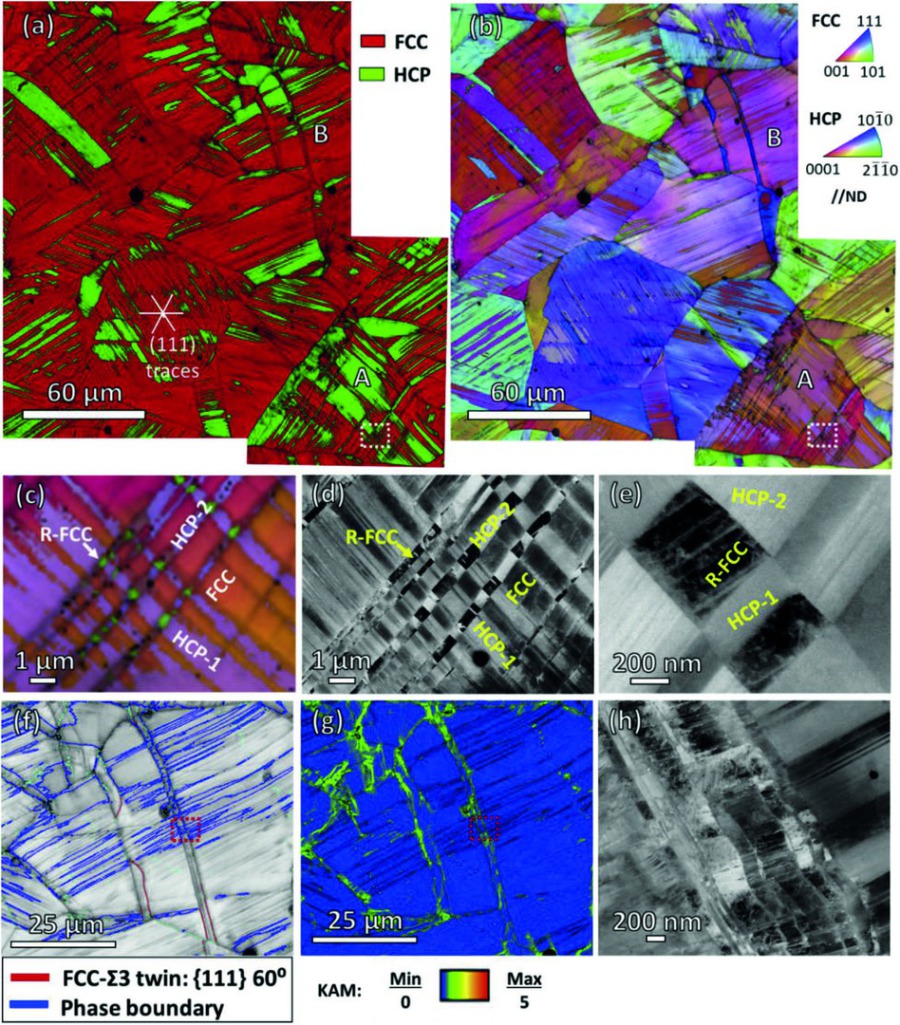 As-rolled microstructure at a thickness reduction of 14%. (a) Phase map; (b) IPF map; (c) and (d) Enlarged IPF map and ECC image of the white rectangular region in grain 'A' showing two HCP variants and reverted FCC phase; (e) ECC image zooming in the rev
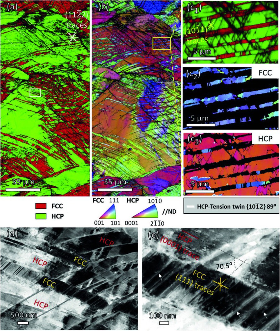 As-rolled microstructure at a thickness reduction of 26%. (a) Phase map showing deformation kink bands in HCP phase developed along pyramidal II {11-22} habit plane; (b) IPF map; (c1) Enlarged phase map superimposed with IQ map of the yellow rectangular r
At 26 % reduction (true strain 30 %)
With further rolling the HCP volume fraction jumps sharply from about 20 to about 60 vol %, as measured by EBSD and XRD (Fig 2). Deformation kink bands with thicknesses of 100 to 500 nm develop inside the HCP phase; trace analysis shows that they run mainly on the {11-22} pyramidal plane, with finer bands on the {10-11} pyramidal plane (Fig 2, Fig 4). Among these bands, alternating layers of HCP and reverted FCC appear. The reverted FCC lamellae show a discontinuous morphology, and a new HCP variant at a 70.5° misorientation to the primary HCP forms adjacent to them. The affected regions have therefore passed through a trifold transformation sequence: FCC to HCP, HCP to FCC, and FCC to HCP again. Partial dislocations are clearly visible in the reverted FCC lamellae (Fig 2).
At 34 % reduction (true strain 42 %)
At 34 % reduction the HCP fraction stays at about 60 vol %: the forward and reverse transformations now compete, and the net fraction saturates (Fig 3). The deformation kink bands propagate widely, and some grow into micro-shear bands with a thickness above 1 µm. Low angle grain boundaries inside these bands mark the formation of nanosized subgrains, and with increasing band thickness the subgrains evolve from elongated to equiaxed, 50 to 80 nm in size (Fig 3, Fig 4). In the remaining large FCC grains, mechanical twins co-exist with the HCP lamellae along the same slip bands.
Crystallographically, the HCP phase develops a near-basal texture: the {0001} pole tilts about 10° toward the rolling direction and the {10-10} pole figure shows a fiber component, while the FCC grains show no obvious preferred orientation (Fig 3). XRD gives HCP lattice parameters of a = 2.54 Å and c = 4.11 Å, a c/a ratio of 1.618 close to the ideal hard-sphere value of 1.633. In this geometry the critical resolved shear stress for basal slip is far lower than for non-basal slip, and the activation of basal, prismatic, pyramidal I, and pyramidal II systems explains the basal pole splitting. Tension twins of the 89° type form in the HCP phase, whereas contraction twins and secondary twins are rare (Fig 3, Fig 4).
At 67 % reduction (true strain 110 %)
At the highest reduction the HCP fraction reaches about 67 vol %, and the volume fraction of micro-shear bands grows from about 10 to about 35 vol % relative to the 34 % rolled state (Fig 5). The bands run in S-shapes through the grains and across grain boundaries. Nano-indentation mapping shows a much higher hardness inside the shear bands, 7 to 8 GPa, versus about 5.5 GPa in the grain interiors. TEM analysis explains this contrast: nanograins of about 50 nm have formed inside the bands, and selected area diffraction shows that both FCC and HCP phases are still present there (Fig 5).
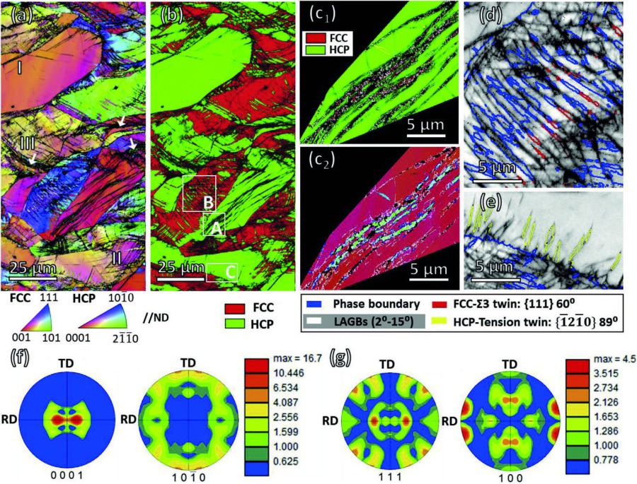 Metastability Interstitial High Entropy Alloy Design Fig 3.jpg As-rolled microstructure at a thickness reduction of 34%. (a) IPF map; (b) Phase map; (c1) and (c2) Enlarged phase map and IPF map of grain 'A' showing reverted FCC phase inside micro-shear. J
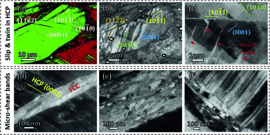 Metastability Interstitial High Entropy Alloy Design Fig 4.jpg Detailed substructures in the 34% rolled specimen. (a) Phase map; (b) ECC image revealing basal {0001}, prismatic {10-10}, pyramidal I {10-11} and pyramidal II {11-22} slip traces in HCP phase
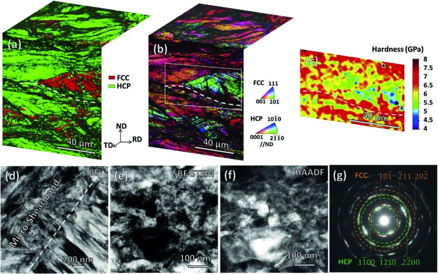 Metastability Interstitial High Entropy Alloy Design Fig 5.jpg As-rolled microstructure at a thickness reduction of 67%. (a) and (b) Psuedo-3D phase map and IPF map; (c) Nano-indentation map of the rectangular region in (b); (d) Bright field (BF) image. J
Mechanism of the bidirectional transformation
The forward transformation follows the S-N orientation relationship: {111}FCC ∥ {0001}HCP and <110>FCC ∥ <11-20>HCP. Both FCC twinning and HCP martensite formation derive from the same Shockley partial dislocations, 1/6<112>: their passage on successive {111} planes produces a twin with a shear of 39°, while their passage on every second {111} plane produces HCP with a shear of 19.5°, half the twinning shear. Where two conjugate HCP variants, separated by 70.5°, cross, their displacement gradients superimpose and create a rigid-body-rotation zone that delivers the full FCC twinning shear, in the sense of the Yang–Wayman analysis. This is the origin of the reverted FCC phase at the lamellae intersections (Fig 10).
The measured variant relationships fit this picture. The misorientation between HCP-1 and HCP-2 is about 70.5°, and the new HCP variant stands at 19.5° and 90° to HCP-1 and HCP-2, respectively, consistent with the six rotationally accessible HCP variant relationships (19.5°, 31.5°, 39°, 51°, 70.5°, 90°) (Fig 10). High-resolution TEM resolves the interfaces directly: the reverted FCC exhibits a twin (CBA) stacking sequence relative to the prior FCC, an FCC atomic layer sits at the HCP/reverted-FCC interface, and stacking faults are present in both phases. The measured crystallographic relationship reads {111}prior FCC ∥ {0001}HCP ∥ {001}reverted FCC and <110>prior FCC ∥ <11-20>HCP ∥ <100>reverted FCC (Fig 11).
The reverse direction is also dislocation-mediated. The interaction of the deformation kink bands with pre-existing stacking faults in the HCP lamellae can dissociate full dislocations; for example, <c+a> pyramidal dislocations can split into two Shockley-type partials bounding a basal stacking fault. The generated partials are the direct source of the HCP-to-FCC reversion, mirroring the way partials drive the forward reaction.
Thermal effects are secondary. The temperature rise estimated from the plastic work is about 15 °C at the 14 % reduction and at most about 276 °C at 67 %, without considering heat losses between passes, while dilatometry places the thermally induced reverse transformation at 380 to 420 °C (Fig 14). Since reverted FCC is already found at a true strain of 15 %, where the temperature rise is negligible, the local stress conditions, not adiabatic heating, drive the reversion. The bidirectional behavior is thermodynamically enabled by the low energy barrier between the FCC and HCP phases in this alloy; the eigenstress field created by cold working, and its spatial inhomogeneity, are sufficient to overcome it.
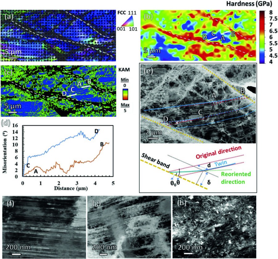 Metastability Interstitial High Entropy Alloy Design Fig 6.jpg (a) IPF map of the tempered specimen with preceding rolling reduction of 67%; (b) Nano-indentation map showing gradient hardness values; (c) KAM map; (d) Misorientation profiles from A to B an
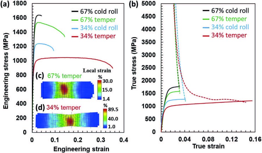 Metastability Interstitial High Entropy Alloy Design Fig 7.jpg (a) Engineering stress-strain curves of the as-rolled specimens at thickness reductions of 34% and 67% as well as of the tempered specimens; (b) True stress-strain plots (solid lines). J. Su,
Tempering: single FCC nanostructure restored
After tempering at 400 °C for 10 min, the HCP martensite reverts to FCC following the S-N relationship. Because the deformation-induced reverted FCC lamellae stand in a twin relationship to the pre-existing FCC layers, while the thermally induced reverted FCC follows the parent stacking sequence, the interface between the two is identified as a twin boundary (Fig 6). The result is a single FCC phase with a hierarchical structure: nano-twins in the grain interiors, submicron dislocation cells of 200 to 500 nm adjacent to the shear bands, and nanocrystals inside the bands.
A matching hardness gradient is measured across the microstructure: about 4.5 GPa at the grain centers, 5.5 to 6 GPa in the regions next to the bands, and 7 to 8 GPa inside the bands (Fig 6). Atom probe tomography shows that carbon is enriched in the shear bands, reaching about 1.0 at. % at some defects, roughly twice the surrounding concentration, because the high dislocation and interface density there provides many trapping sites and the dissipative heating during band formation accelerates the decoration; Fe, Mn, Co, and Cr remain distributed homogeneously. The carbon segregation contributes to the ultra-high hardness of the bands (Fig 13). The average shear strain in the 2 µm-thick shear bands is about 1.8 to 2. It bends the adjacent twin lamellae and drives geometrically necessary dislocations into the submicron cells next to the bands, consistent with the measured misorientation gradients (Fig 6).
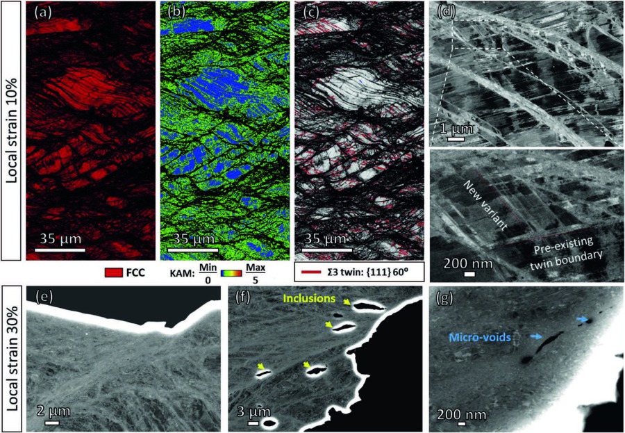 Metastability Interstitial High Entropy Alloy Design Fig 8.jpg Deformation microstructures of the tempered 67% rolled specimen upon tensile loading at local strains of 10% (a)–(d) and 30% (e)–(g). (a) Phase map; (b) IPF map; (c) IQ map. J. Su, X. Wu, D. R
Mechanical properties
|
Condition |
Yield strength (MPa) |
UTS (MPa) |
Total elongation (%) |
|
67 % rolled |
1500 |
1600 |
5 |
|
67 % rolled + tempered |
1300 |
1500 |
14 (uniform ~3) |
|
34 % rolled |
1000 |
1200 |
~10 |
|
34 % rolled + tempered |
900 |
1050 |
35 (uniform 14) |
The mechanical response of the four conditions is summarized in the table above (Fig 7). The 67 % rolled material is very strong, with a yield strength of 1.5 GPa and an ultimate tensile strength of 1.6 GPa, but it offers only 5 % total elongation. Tempering lowers the strength slightly, to 1.3 GPa yield and 1.5 GPa ultimate, and raises the total elongation to 14 %, yet the uniform elongation stays around 3 %. Tempering thus improves only the post-necking ductility: the work hardening rate remains too low to prevent early necking. In the near-fracture region, shear bands produce necking steps along the edge of the specimen, and micro-voids and cracks propagate along the micro-shear bands (Fig 8). In this condition both TRIP and TWIP are largely suppressed. Deformation-induced HCP martensite is barely visible at a local strain of 10 %, and the twin boundary length per unit area stays at about 0.31 to 0.32 µm/µm² up to that strain. The tight twin spacing leaves no room for the partial dislocation glide that would nucleate martensite, and the contribution of twinning to work hardening is correspondingly limited (Fig 8).
The 34 % rolled material behaves differently. It has a lower yield strength (1 GPa) and ultimate tensile strength (1.2 GPa), but its total elongation of about 10 % is roughly twice as high. After tempering, the yield strength and ultimate tensile strength drop to 900 MPa and 1.05 GPa, while the ductility improves dramatically, to a total elongation of 35 % at a uniform elongation of 14 %. The work hardening rate of this condition is the strongest of the four, with a further slight increase near 10 % strain (Fig 7). Under tensile loading, HCP martensite nucleates at a local strain of 10 % along the pre-existing twin boundaries, which act as glide planes for the transforming partial dislocations; the HCP fraction grows from 3.8 to 4.7 vol % up to a local strain of 40 %, and the twin fraction increases with loading as well. Both TRIP and TWIP therefore remain active in this nanostructured state, and the larger spacing between the pre-existing nano-twins allows more dislocation accumulation and stronger dislocation–twin interactions, which feed the work hardening (Fig 9).
The practical conclusion is that the rolling and tempering combination must be tuned so that both TRIP and TWIP remain available in the nanostructured state. The 34 % rolled and tempered iHEA achieves exactly this, and it is the condition that delivers the best strength–ductility synergy.
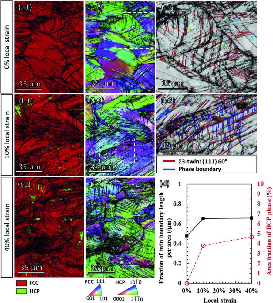 Metastability Interstitial High Entropy Alloy Design Fig 9.jpg Deformation microstructures of the tempered 34% rolled specimen during tensile testing at local strains of (a) 0%, (b) 10%, and (c) 40%, where (1) refers to phase maps, (2) IPF maps, and (3) e
Design principles
The study proposes a general route to bulk nanostructured alloys with superior strength–ductility combinations. First, the stacking fault energy and phase stability of a multi-principal-element alloy should be tuned toward the thermodynamic stability limit, so that load triggers sequential athermal forward and reverse martensitic transformations. Second, the non-equiatomic HEA compositional space makes such metastable states reachable, and the interstitial carbon addition in the FeMnCoCr system is part of the recipe. Third, a moderate cold rolling of 26 to 34 % builds the dual-phase nano-laminated precursor, while a 67 % reduction produces micro-shear bands filled with 50 nm nanocrystals. Fourth, a short temper at 400 °C for 10 min reverts the HCP back to FCC and leaves a single-phase FCC nanostructure of nano-twins, nano-(sub)grains, and nano-crystals. Finally, the optimum strength–ductility combination (1.05 GPa ultimate tensile strength at 35 % total elongation) is obtained in the microstructure where both TRIP and TWIP remain active during tension.
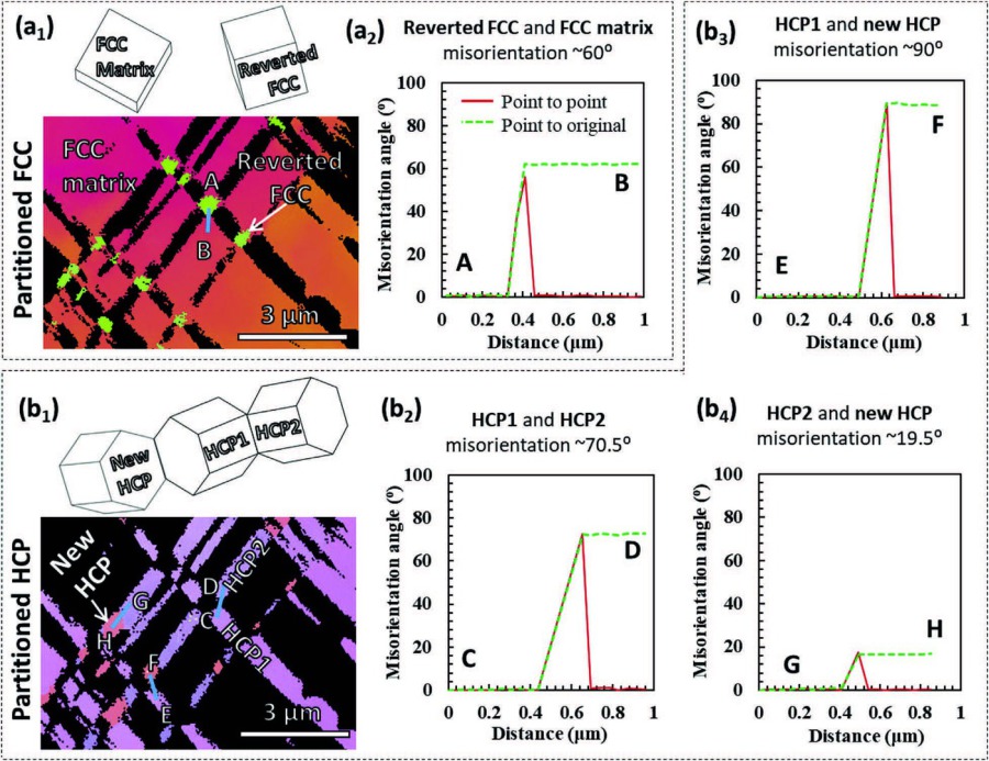 Metastability Interstitial High Entropy Alloy Design Fig 10.jpg Microstructure and misorientation relationship of two-crosshatched HCP lamellae and reverted FCC in the 14% rolled specimen. Partitioned IPF maps of (a1) FCC phase and (b1) HCP phase; Misorie
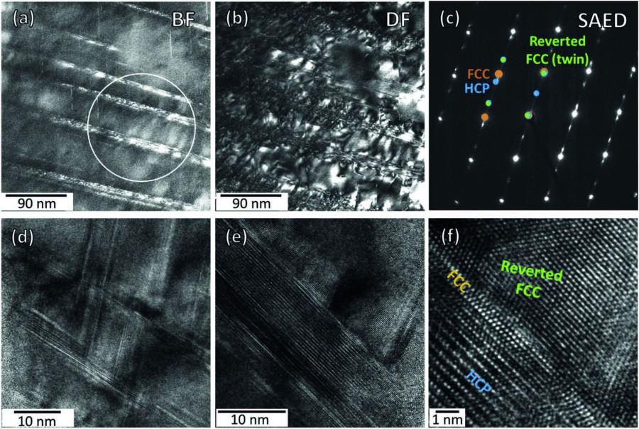 Metastability Interstitial High Entropy Alloy Design Fig 11.jpg Details of the substructure of the 34% rolled specimen. (a) BF image and DF image revealing alternating layers of HCP martensite and reverted FCC phase; (c) Selected area diffraction (SAD) pa
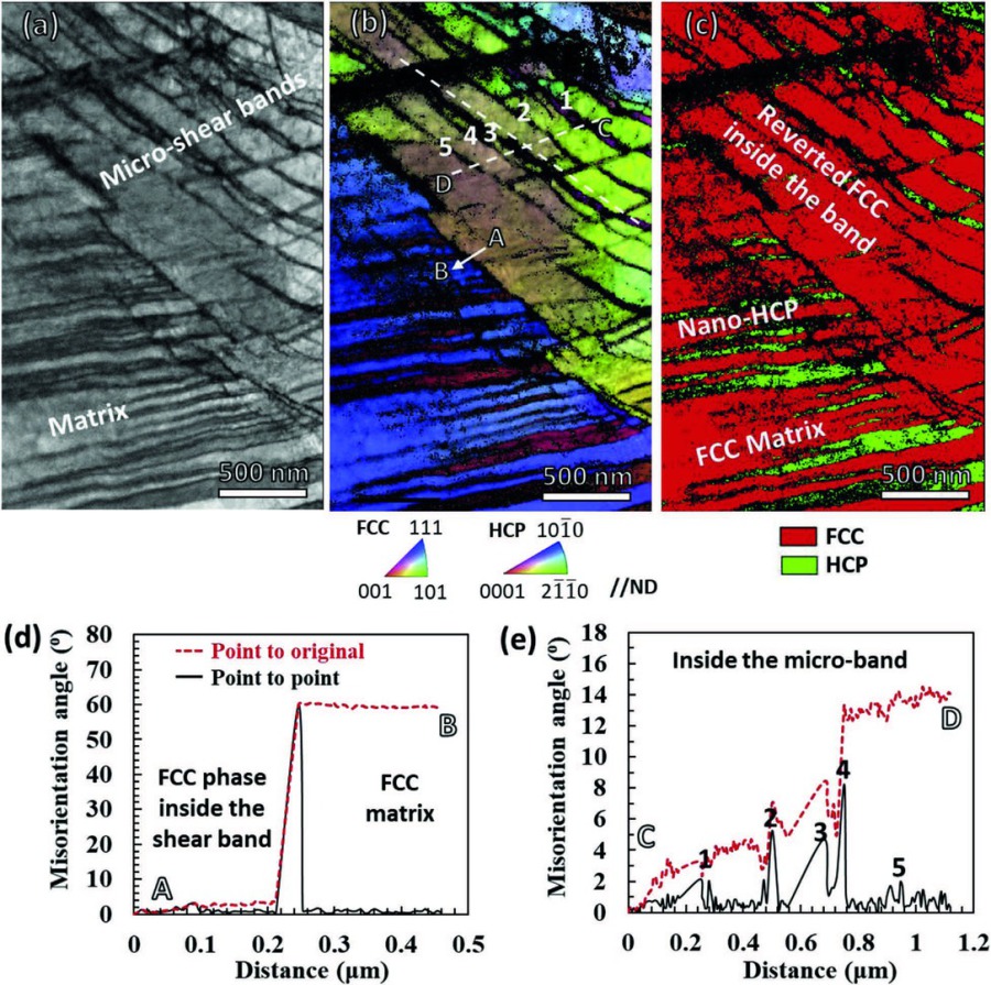 Metastability Interstitial High Entropy Alloy Design Fig 12.jpg Transmission-EBSD microstructures of the 34% rolled specimen. (a) IQ map; (b) IPF map revealing substructure inside micro-shear bands; (c) Phase map showing nano-layers of HCP martensite in F
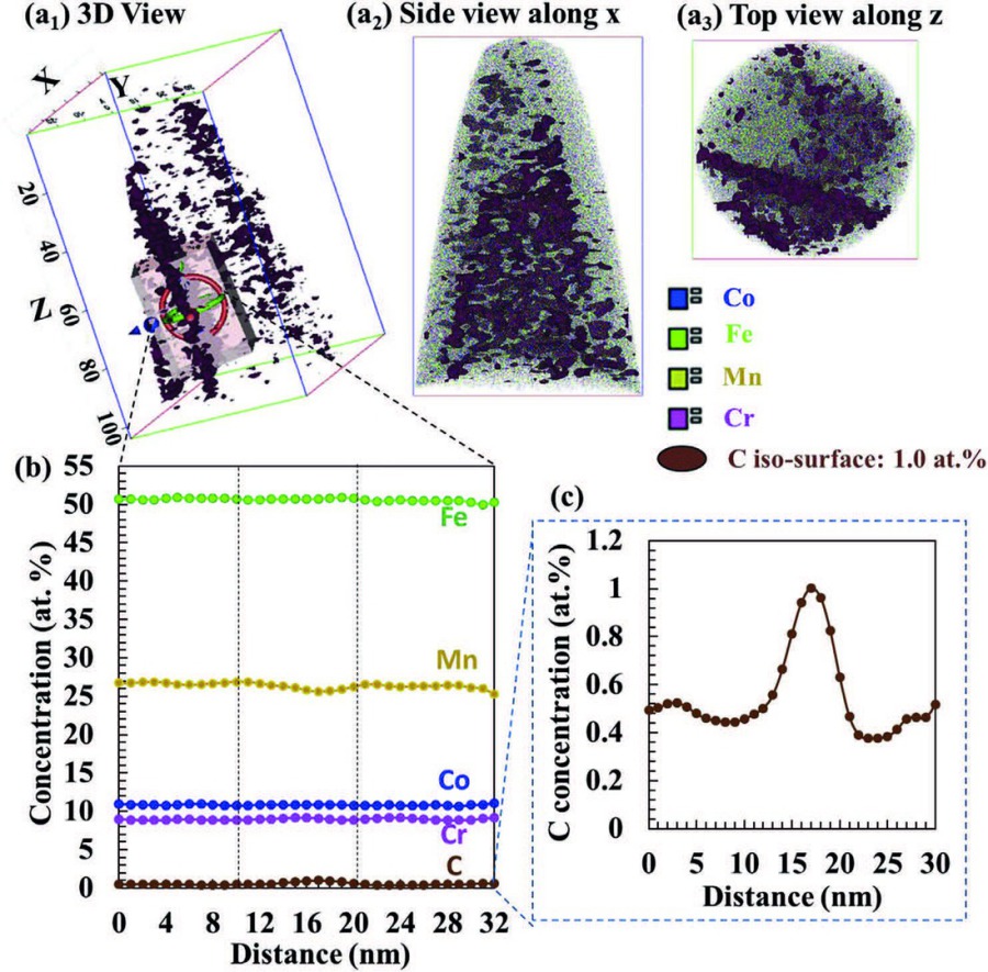 Metastability Interstitial High Entropy Alloy Design Fig 13.jpg APT analysis of the shear-banded region of the tempered 67% rolled specimen. (a) 3D view, 2D side view and top view of the tip with carbon iso-surface at 1.0 at.%; (b) Concentration profile o
 Druckversion