Sheet Forming Simulations using Crystal Plasticity Finite Elements Methods
Crystal plasticity simulation study on the influence of texture on earing in steel
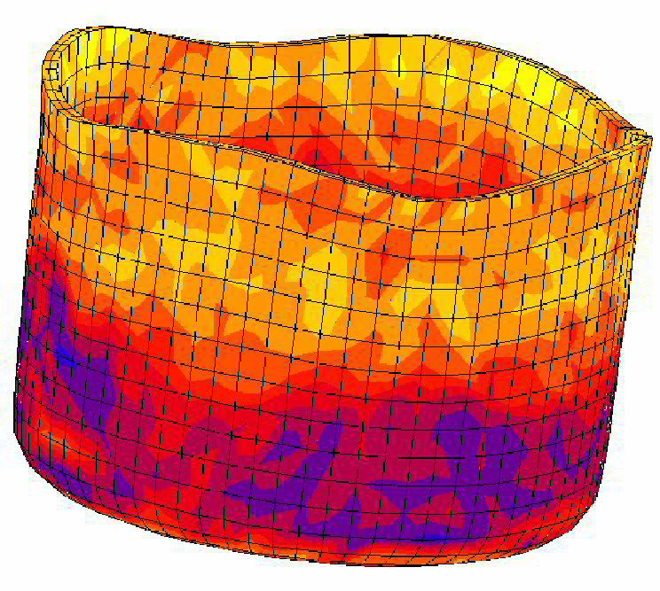
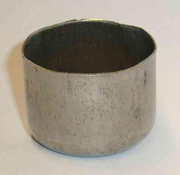
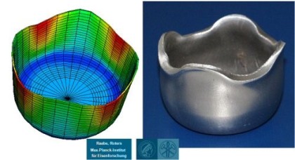
This is an example of a numerical study on the influence of crystallographic texture on the earing behavior of a low carbon steel during cup drawing. The simulations are conducted by using the texture component crystal plasticity finite element method (using the free texture simulation software package DAMASK) which accounts for the full elastic-plastic anisotropy of the material and for the explicit incorporation of crystallographic texture including texture evolution and texture update. Several important texture components that typically occur in commercial steel sheets were selected for the study. By assigning different spherical scatter widths to them the resulting ear profiles were calculated under consideration of texture evolution. The study reveals that 8, 6, or 4 ears can evolve during cup drawing depending on the starting texture. An increasing number of ears reduces the absolute ear height. The effect of the orientation scatter width (texture sharpness) on the sharpness of the ear profiles was also studied. It was observed that an increase in the orientation scatter of certain texture components entails a drop in ear sharpness while for others the effect is opposite.
 Crystal plasticity meets yield surface mechanics: Erichsen sheet metal forming test
Introduction to polycrystal anisotropy and yield surface functions
The texture-related shape anisotropy of cup drawn metallic sheet parts is referred to as earing or ear formation. It is a characteristic phenomenon associated with the crystallographic texture and the resulting elastic-plastic anisotropy of metals. Sheet steels usually have pronounced textures which they inherit from the preceding processing steps such as hot rolling, cold rolling, and heat treatment.
What is a yield surface in crystal plasticity?
A yield surface describes a typically five-dimensional entity of stress states (which are together referred to as 'surface') in the six-dimensional space of the stress tensor at which (irreversal)
elastic-plastic deformation occurs. It is for this general phenomenological concept irrelevant which kind of material is described.
Any stress state inside of the yield surface entails elastic deformation only.
When a stress state is reached that lies exatly on the yield surface the material has reached its yield point and the material starts to deform plastically.
No stress state above the yield surface can exist. When the stress is increased further than the material's internal resistance to plastic flow must also grow, which is referred to as strain
hardening or work hardening.
Thus, further deformation of the material causes the stress state to remain on the growing yield surface, even though the shape and size of the surface may change as the plastic deformation evolves
for instance due to the gradual evolution of the crystallographic texture what you to changes in the topological arrangement of the different constituents and phases.
Which types of yield surface description methods exist in crystal plasticity?
Various concepts exist to introduce texture-related sheet anisotropy into finite element models for sheet forming. The initial material anisotropy existing before sheet deformation can be
incorporated either through an anisotropic yield surface function or directly via the incorporation of crystallographic texture models into the finite element codes. The anisotropic yield surface
models can be classified into two groups. The first one comprises empirical and phenomenological anisotropic yield surface equations, such as the equations of Hill from 1948 and 1979, Hosford,
Barlat, or Barlat and Lian to name but a few important ones. These yield surface functions are formulated as convex higher-order polynoms, i.e. they take an empirical view at plastic anisotropy. The
physical nature of anisotropy can be incorporated into these concepts for instance by fitting the corresponding polynomial coefficients with the aid of texture-based strain-rate or self-consistent
homogenization methods or with anisotropy parameters obtained from mechanical tests.
The second type of yield surface models is directly formulated as texture-based yield loci the coefficients of which can be directly expressed in terms of the texture-based mechanical models in
conjunction with experimentally determined orientation distributions.
The advantage of yield surface concepts for mechanical anisotropy predictions are relatively short calculation times, when implemented into finite element models, although one must recall that the
measurement of the mechanical anisotropy parameters and the fitting of the anisotropy coefficients must be added to the total time required for a prediction.
The main disadvantage of the yield surface concept is that they do not consider that the inherited sheet starting textures may evolve further in the course of sheet forming. This means that reliable
anisotropy simulations should incorporate the starting texture as well the gradual update of that texture during deep drawing operations. Some recent results indeed indicate that the change in
crystallographic texture during deep drawing may be relevant for the resulting ear shapes.
How is crystallographic texture evolution considered in crystal plasticity - based yield surface mechanics?
In order to take into account texture evolution during deformation, the crystallographic texture models have been developed. These models can be roughly classified into three groups, namely, combinations of a Taylor-type strain-rate homogenization model and finite element formulations, the crystal plasticity finite element model, and texture-function based crystal plasticity finite element models.
The approach of combining a Taylor model with a finite element model was for instance suggested introduced by Gottstein. In this approach the deformation tensor after each strain increment is used to prescribe the boundary conditions for a corresponding Taylor simulation using full constraints or coupled full constraints/grain interaction homogenization model. Each of the finite elements contains its representative crystallographic texture information in the form of a large set of discrete grain orientations. The Taylor factor calculated from homogenization is fed back into the finite element simulation as a correction factor for the flow stress in the ensuing simulation step. The particular strength of this method lies in the exact simulation of texture evolution under intricate boundary conditions.
The crystal plasticity finite element models consist in a direct implementation of crystallographic slip kinematics into finite element models. It was first suggested by Peirce, Needlemann, and Asaro. Based on their early work a fully-implicit time-integration scheme was developed by Kalidindi and implemented in commercial finite element software in the form of a user-defined subroutine. Crystal plasticity finite element models provide a direct means for updating the material state via integration of the evolution equations for the crystal lattice orientation and the critical resolved shear stress. The deformation behavior of the grains is at each integration point determined by a crystal plasticity model, which accounts for plastic deformation by crystallographic slip and for the rotation of the crystal lattice during deformation.
Crystal plasticity finite element models represent elegant tools for detailed simulation studies of texture evolution under realistic boundary conditions. Each integration point can represent one single orientation or even a large set of discrete grain orientations when combined with an appropriate homogenization assumption. Although the latter case (mapping of a representative texture on one integration point) is principally feasible, it entails long calculation times, rendering the method less practicable for industry-scale applications.
For rendering the crystal plasticity finite element models more flexible with respect to the treatment of large polycrystalline entities Raabe and Roters recently introduced a texture component crystal plasticity finite element model. The basic idea of this method consists in using a more effective way of describing the texture of macroscopic samples at each integration point, turning the method into a texture component crystal plasticity finite element method. More details on this approach are given in the ensuing section.
Which types of slip systems are relevant for texture sheet and forming predictions in body centred cubic steels?
The main feature of crystal plasticity in bcc steels and other bcc transition metals is the occurrence of {110}, {112}, and {123} slip planes, all of which contain the 1/2 <111>
Burgers vector. Although the activation of these slip systems is widely
accepted for bcc single crystal deformation, three uncertainties remain. First, by the use of transmission electron microscopy (TEM) it is not always possible to distinguish
between {123} slip and combined or alternating {112} and {110} slip. Second, results stemming from TEM investigations do not always provide statistically reliable information
since - inherent to the technique - only a very small volume fraction of material is studied and the identification of a certain slip system does not yet give any information
about its quantitative contribution during plastic deformation. Third, the criterion for selecting the active s!ip systems in polycrystals is fundamentally different from that
which rules the plastic deformation of single crystals. Accounting for these uncertainties, the application of quantitative texture analysis for the investigation of
the contribution of { 123} slip systems during plastic deformation of bcc metals represents a useful approach.
Materials Science and Technology, May 1995 Vol. 11, page 455
Materials Science and Technology May 199[...]
PDF-Dokument [1.4 MB]
How is the partitioning of stress and strain among ferrite and martensite in dual phase steels during deformation ?
Dual phase steels consisting of soft ferrite and hard martensite show pronounced partitioning in both stress and strain among these two phases.
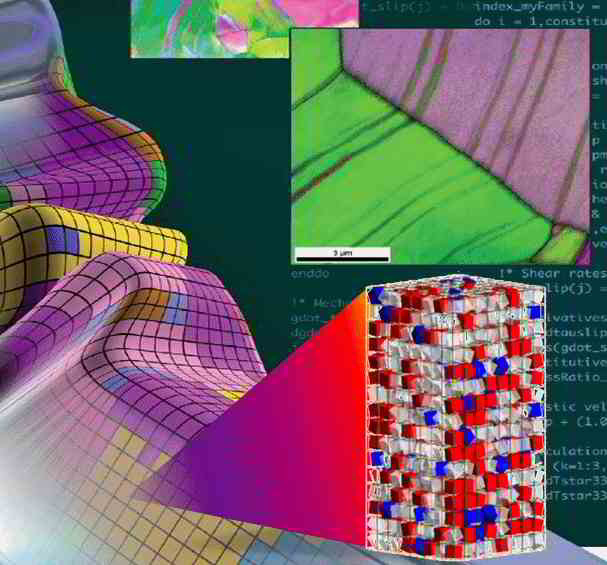
We used an integrated experimental–numerical methodology that allows the analysis of strain and stress partitioning in these steels. This methodology
includes a number of improvements with respect to previous efforts in terms of the complexity of the microstructure handled, the resolution at which the microstructure and deformation is tracked, the fidelity with which the microstructure is mapped and modeled, and particularly the interplay between the experiments and the simulations. The corresponding DP steel analysis revealed that:
1) Concurrent strain and microstructure mapping can be achieved to the point of damage nucleation, at high resolution and field-of-view, by the in situ testing method.
2) Physically based microstructure models can be created, and the corresponding crystal plasticity problems numerically solved, using the DAMASK framework and the recently
developed advanced spectral method suitable for heterogeneous material behavior.
3) For DP steels, the importance of martensite morphology and interconnectivity is observed to be critical, especially for harder (i.e. high-carbon) martensite.
4) High strain heterogeneity is observed in the ferrite, which relates to the in-grain microstructural heterogeneities arising from processing,
Acta Materialia 81 (2014) 386
Acta Mater 81 (2014) 386 dual phase stee[...]
PDF-Dokument [1.6 MB]
Sheet forming simulations: Applications using yield surface mechanics based on crystal plasticity
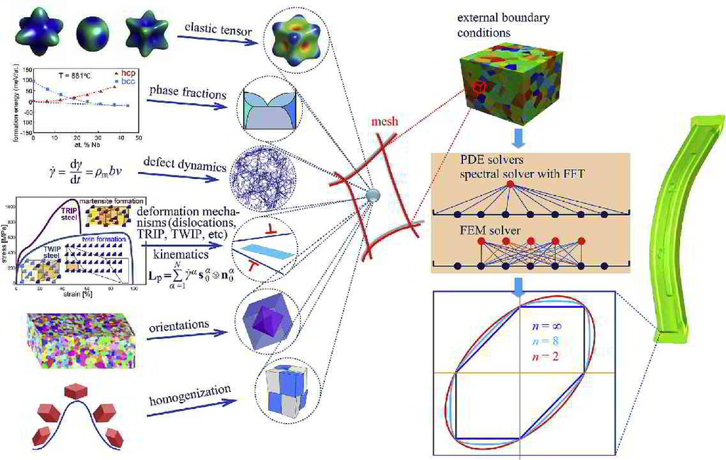
Due to their complex thermo-mechanical treatments, polycrystalline metals are as a rule crystallographically textured, and hence their mechanical properties are anisotropic. The directionality of the mechanical properties must be taken into account when modeling metal forming operations. The anisotropy induced by plastic strain during forming operations is small compared to that induced by the thermo-mechanical treatment and negligible for most applications. Crystal plasticity (CP) models which use the crystallographic texture and the intrinsic single crystalline anisotropy as input can accurately describe the anisotropic behavior of polycrystalline materials and naturally consider the stress and strain partitioning among different phases, grains, and subgrains (Roters et al., 2010). However, the long computation times required to integrate the underlying constitutive equations render their use infeasible for engineering simulations of large scale components. Due to their high efficiency and straightforward implementation, analytical yield functions are thus used instead of full-field CP simulations at the engineering scale to describe the anisotropy of materials.
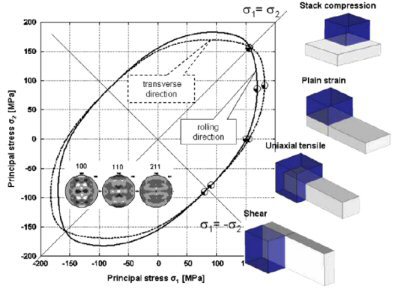
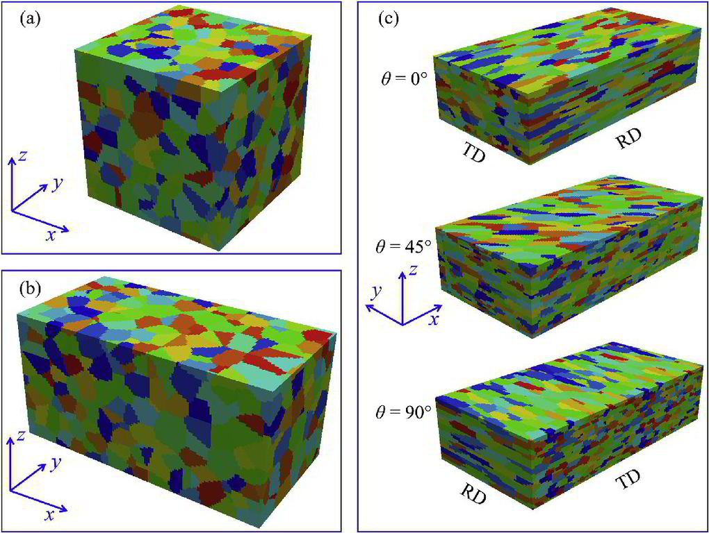
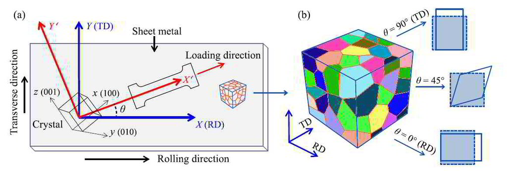
 Reference frame set-up for conducting simulated tensile tests in arbitrary loading directions and the corresponding texture rotation in the virtual uniaxial tensile experiments.
Starting with the first anisotropic yield function proposed by von Mises (1928), various yield functions have been established to describe the flow behavior of different material classes. The
quadratic anisotropic yield function developed by
Hill (1948) was validated by numerous experiments and is well suited for body centered cubic (bcc) materials, especially for steels (Hill,1990). However, it can not accurately describe the yield
behavior of face centered cubic (fcc) metals, e.g., aluminum alloys (Hosford,1988), as only higher order ansatz functions are capable of predicting the rather angular form of yield
surfaces and the so-called “anomalous behavior” (Darrieulat and Piot, 1996), i.e., the experimental observation that the equi-biaxial yield stress is higher than the uniaxial yield stress
while the r-value is below 1.0 (Woodthorpe and Pearce, 1970). To overcome these limitations, Hill (1979) and Hosford (1985) proposed non-quadratic anisotropic yield functions. Later, Barlat
and Lian (1989), Barlat et al. (1991, 1997, 2003, 2005), Karafillis and Boyce (1993), Banabic et al. (2003), Bron and Besson (2004) introduced further improved formulations, where linear
transformations of the stress tensor are used to describe the anisotropy (Barlat et al., 2007).
For material models used in a commercial context, it is preferable that only a small set of simple and low-cost tests, e.g., uniaxial tensile tests, are necessary for calibration (Lademo et
al.,1999). The ability of advanced yield functions to describe the mechanical anisotropy of various material classes, however, comes at the price of requiring many parameters.
Improved flexibility and accuracy therefore makes the parameter identification process more challenging as more experimental results are needed. These experiments are expensive, time
consuming, and sometimes very difficult to perform, e.g., when out-ofplane
properties of sheet metals are required. Additionally, since no standards are defined for most of these experiments, evaluation of a parameter set requires an in-depth knowledge about the
details of the fitting procedure that was employed to retrieve it.
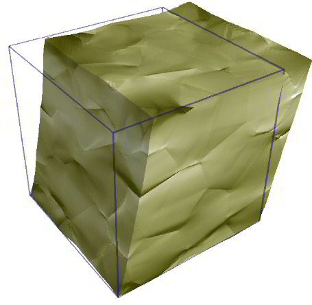
 RVEs with 500 randomly distributed grains.
Besides considering experimental results, numerical models are frequently used to examine the mechanical response of polycrystalline materials. Micromechanical models based on CP theory play
a significant role in understanding yielding and anisotropy of metals, as well as in evaluating yield surface models. The earliest of such approaches, proposed by Sachs (1929),
uses an iso-stress approach and assumes the same resolved stress on the slip systems with the highest resolved shear stress in all grains within the polycrystalline aggregate. In contrast, the
full-constraint (FC) model developed by Taylor (1938) is based on the iso-strain assumption, i.e., all grains within an aggregate experience the same state of deformation. The FC TAYLOR
model
was elaborated further by Bishop and Hill (1951), and was used as the TAYLOR-BISHOP-HILL (TBH) model by many researchers to validate yield functions (Hosford, 1972; Barlat and Lian, 1989; Barlat
et al., 1997) or to generate the analytical expressions for plastic potentials and yield surfaces of anisotropic polycrystalline materials (Gambin, 1991; Van Houtte, 1994, 2001; Li et al.,
2003; Van Houtte and Van Bael, 2004; Kowalczyk and Gambin, 2004; Van Houtte et al., 2009). It should be noted that the SACHS model satisfies the stress equilibrium condition across the grains
but violates the compatibility condition between them, while, in contrast, the TBH model violates the stress equilibrium condition but satisfies the compatibility condition
among differently oriented grains (Kocks, 1958). The deformation behavior of real polycrystals, where both, compatibility and equilibrium are fulfilled, is in-between these two extremes
(Sachtleber et al., 2002). The former model therefore sets the lower bound and the latter is the upper bound of the observed behavior.
Although the TAYLOR model shows good performance in the prediction of deformation textures, it is not fully realistic due to the violation of stress equilibrium. Various relaxed-constraint (RC)
TAYLOR models were developed relieving the rigid deformation constraint in TAYLOR's iso-strain hypothesis (Honneff and Mecking, 1981; Kocks and Chandra, 1982; Raphanel and Van
Houtte, 1985; H€olscher et al., 1991, 1994; Raabe, 1995c). Also, a number of grain cluster models were introduced such as the LAMEL model, the advanced LAMEL (ALAMEL) model (Van Houtte et al.,
1999, 2002, 2005), the grain interaction (GIA) model (Raabe,1995a,b; Raabe et al., 2002b; Crumbach et al., 2006), and the relaxed grain cluster (RGC) model (Tjahjanto et al., 2010).
Another important class of homogenization schemes is based on the self consistent (SC) approach which was originally proposed by Kr€oner (1958) for the elastic case and later extended to the
elastoplastic (Hill,1965) and viscoplastic (Hutchinson, 1976) cases. In the SC theory, each grain within a polycrystalline aggregate is considered to be an ellipsoidal inclusion
embedded in the surrounding homogeneous equivalent medium (HEM). Such models satisfy the stress equilibrium and the deformation compatibility simultaneously as they allow for different
deformation responses in each grain depending on the relative stiffness between the grain and the HEM. Among the various SC models, the visco-plastic self consistent (VPSC) model
developed by Molinari et al. (1987) and extended by Lebensohn and Tom!e (1993, 1994) has been widely used to simulate plastic behavior and texture evolution of polycrystalline materials
(Lebensohn et al., 1996, 1998; Segurado et al., 2012; Knezevic et al., 2013). Although the SC models relieve the drawbacks associated with the TAYLOR type models, further microstructural
aspects of the deformation, such as local grain interaction and intra-grain inhomogeneities of the micromechanical fields, are not accessible to these models (Zhao et al., 2007; Lebensohn et
al., 2012).
Recently, full-field CP models, which are capable of incorporating additional morphological information beyond crystallographic texture, either employing the finite element method (FEM,
CPFEM) (Raabe et al., 2001; Raabe and Roters, 2004; Dawson et al., 2005; Zhao et al., 2008; Kanjarla et al., 2010; Roters et al., 2010; Van Houtte et al., 2011; Zhang et al., 2015a) or a
spectral method using fast FOURIER transformation (FFT) (Lebensohn et al., 2012; Kanjarla et al., 2012; Eisenlohr et al., 2013; Tasan et al., 2014a; Shanthraj et al., 2015) based solvers have
become computationally feasible for the simulation of representative volume elements (RVEs). The merits of such full-field approaches include: (i) fulfillment of both, stress
equilibrium and strain compatibility at grain boundaries; (ii) representation of a real grain morphology as long as the discretisation is fine enough; (iii) consideration of the local grain
interactions and intra-grain inhomogeneities associated with plastic deformation. The main drawback of the full-field CPFEM is the computational cost associated with the large number of material
points needed for the simulation of a sufficiently highly resolved polycrystalline RVE. Compared with their FEM counterparts, spectral methods using FFT show much higher efficiency in
solving boundary value problems (BVPs) (Prakash and Lebensohn, 2009; Lebensohn et al., 2012; Eisenlohr et al., 2013), at the cost of being limited to periodic boundary conditions (BCs).
The spectral method was successfully used in simulating crystallographic texture evolution (Liu et al., 2010), modeling micromechanical
response of two-phase materials (Lee et al., 2011), predicting internal lattice strain distributions in stainless steel (Kanjarla et al., 2012), the local stress partitioning of dual-phase steel
(Tasan et al., 2014b).
Virtual laboratory approaches, using fine-scale full-field modeling, e.g., CP models for the calibration of yield loci and the identification routines required for acquiring the parameters of
advanced phenomenological yield functions, enable us to combine advantages of both methods, i.e., the accuracy of CP models and the computational efficiency of analytic yield functions
(Raabe, 2000; Kraska et al., 2009; Van Houtte et al., 2009; Lademo et al., 2009; Helm et al., 2011). In such a scheme, virtual tests are performed using a CP model to provide yield stress points
for the parameter identification of yield functions. Unlike mechanical experiments, which are limited to certain accessible deformation modes, the virtual CP tests are able to provide data
for any deformation modes, which renders the approach especially attractive for identifying for instance the out-of-
plane mechanical response of sheet metal materials. Barlat and Chung (2005) adopted the TBH model to generate the flow surfaces based on crystallographic texture measurements. Barlat et al.
(2005) used the flow stress curves predicted by a VPSC model under different applied BCs to evaluate the out-of-plane properties of a 2090-T3 AleLi alloy sheet, where the complete parameter
set of the Yld2004-18p yield function was identified by a combination of results from experiments and VPSC simulations. Plunkett et al. (2006) used the VPSC model to identify the parameters of
yield function developed by Cazacu et al. (2006) and simulated the change of anisotropy parameters associated with the twinning induced texture evolution in zirconium. Grytten et al. (2008)
evaluated different parameter identification methods for the Yld2004-18p yield function, i.e., different combinations of mechanical experimental data and virtual test data obtained by using the
FC TAYLOR model. Even though both, mechanical and virtual test results could be satisfactorily reproduced by the adjusted yield function, the authors suggested that more advanced CP models
are needed because the FC TAYLOR model lacks the ability to quantitatively reproduce the mechanical experiments. Rabahallah et al. (2009) adopted a texture based procedure to identify the
parameters of the plastic strain rate potential Srp2004-18p. More recently, Zhang et al. (2015b) investigated the anisotropy of an AA1050
aluminum sheet by using different CP models, including the FC TAYLOR model, the ALAMEL model, the ALAMEL Type III model, the VPSC model, and a CPFEM approach. Employing various calibration
methods corresponding to different combinations of uniaxial tensile data and virtual yield stress points, the authors identified the parameters of the Yld2004-18p yield function and
concluded that the FC-TAYLOR, VPSC, and ALAMEL models are not capable of capturing the plastic anisotropy of the AA1050 aluminum sheet. These CP models were also employed to predict the plastic
anisotropy of AA3103 sheets in the cold-rolled and fully annealed conditions (Zhang et al., 2014). Gawad et al. (2015) adopted a ALAMEL CP model as the basic constituent of the virtual
laboratory to calculate the data for the identification of the BBC2008 yield function parameters.
Due to the crucial role of the initial crystallographic texture, the success of a virtual laboratory approach critically depends on the accurate and representative characterization and
representation of the underlying microstructure. Full-field CPFEM models are able to use arbitrary complex microstructures and they do account for grain-to-grain interactions and
intragranular field variations (Beaudoin et al., 1995, 1996; Raabe et al., 2003). However, the large number of degrees of freedom and elements required by CPFEM simulations to properly
account for all relevant fine-scale microstructure features with a sufficient level of fidelity renders the calculation times often unaffordable. Its high numerical efficiency as compared
to CPFEM makes the spectral integration method in conjunction with CP constitutive equations thus a promising alternative
candidate, since it combines accuracy of the CPFEM approach with affordable computation times. This especially holds as the required periodic BCs are applicable to the case of RVE simulations.
Therefore, the use of spectral solvers in conjunction with CP constitutive models provides quantitative microscopic mechanical insights on the plastic anisotropy of metallic polycrystals
at affordable computational costs. This work aims to introduce a full-field CP based virtual laboratory which is able to probe the anisotropic properties of
metals and further relieve the parameter identification of advanced yield functions. An efficient spectral solver in conjunction with a CP model (Roters et al., 2012; DAMASK, 2014) is used to
perform full-field virtual experiments on highly resolved1 microstructures. The anisotropic behavior of an AA3104 aluminum alloy with two different initial crystallographic textures and
grain morphologies is investigated and the parameters of four widely used yield functions, namely, Yld91 (Barlat et al., 1991), Yld2000-2D (Barlat et al., 2003), Yld2004-18p (Barlat et al.,
2005), and Yld2004-27p (Aretz et al., 2010) are determined. The methodology includes: mapping of the microstructure obtained from material characterization of the desired materials to a
high resolution RVE; applying a large number of arbitrary BCs on the RVE to obtain yield stress points; and identifying the parameters of the yield functions using these stress probing
points.
International Journal of Plasticity 80 (2016) 111-138
Intern J Plasticity 80 (2016) 111 Zhang [...]
PDF-Dokument [5.3 MB]
 virtual laboratory using high resolution crystal plasticity simulations to determine the initial yield surface for sheet metal forming operations
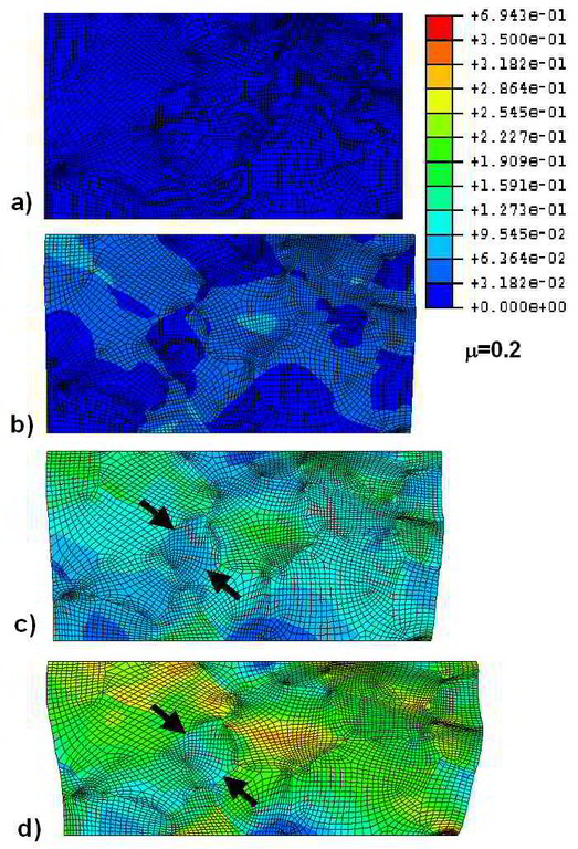
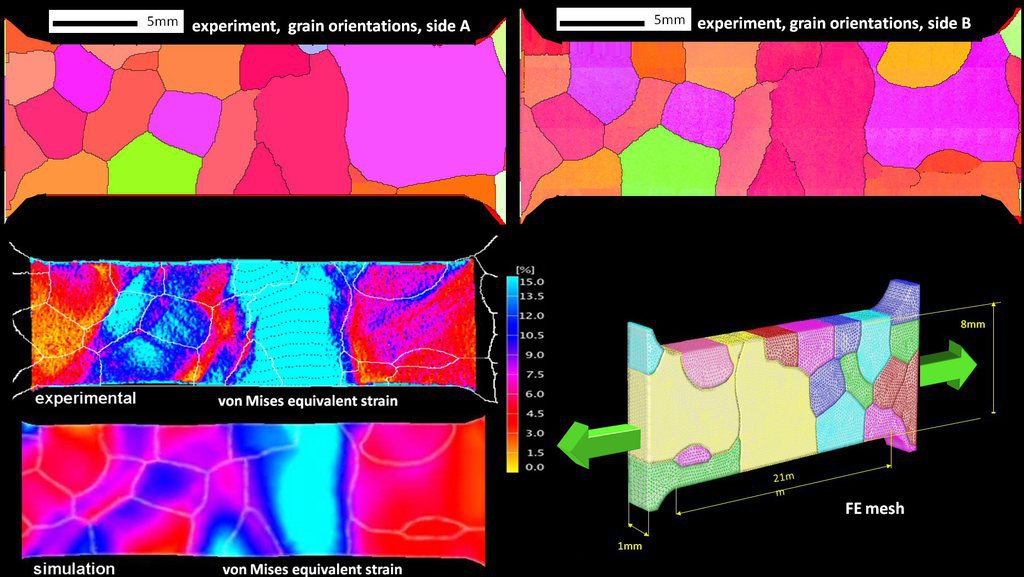
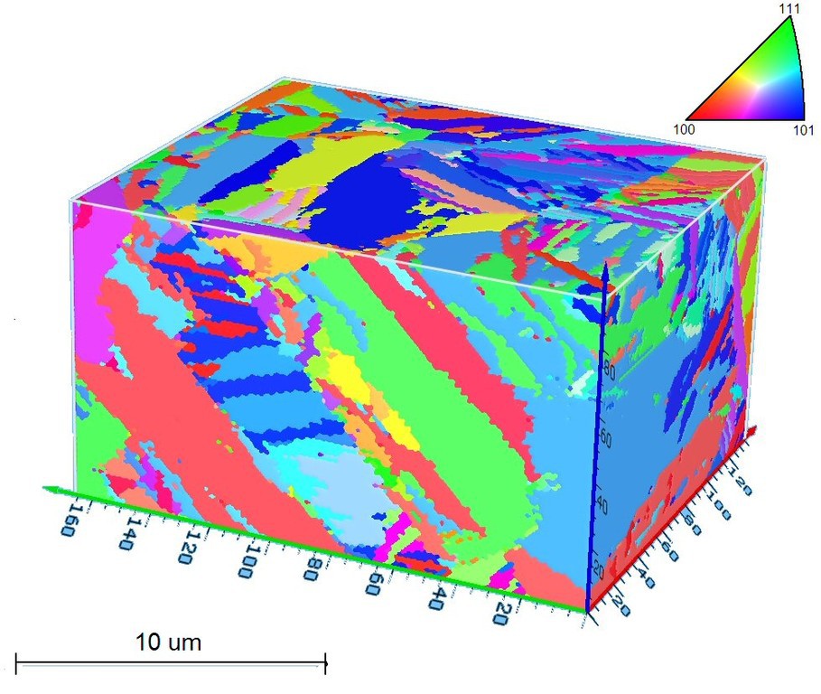
 D. Raabe, M. Sachtleber, H. Weiland, G. Scheele, and Z. Zhao: Acta Mater. 51 (2003) 1539-1560 Grain-scale micromechanics of polycrystal surfaces during plastic straining
D. Raabe,, F. Roters and Y. Wang
Materials Science Forum Vols. 495-497 (2005) pp. 1529-1534
Simulation of earing during deep drawing of bcc steel by use of a texture component crystal plasticity finite element method
Materials Science Forum Vols. 495-497 (2[...]
PDF-Dokument [271.5 KB]
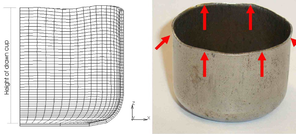
Shape anisotropy of drawn parts may occur in the form of earing. It is a phenomenon which is associated with the texture and the resulting elastic-plastic anisotropy of metals [1-16]. Sheet
steels usually have pronounced textures which they inherit from the preceding processing steps such as hot
rolling, cold rolling, and heat treatment [17-23]. Various concepts exist to introduce texture-related sheet anisotropy into finite element models for
sheet forming. The material anisotropy existing before sheet deformation can be incorporated either through an anisotropic yield surface function [e.g. 24-28] or directly via the use of crystal
plasticity finite element models. The crystal plasticity finite element models are a direct implementation of crystallographic slip kinematics into finite element models. It was first
suggested by Peirce,
Needlemann, and Asaro [29-32]. Based on their work an implicit time-integration scheme was developed by Kalidindi et al. [33] and implemented in commercial finite element software in
the form of a user-defined subroutine. Crystal plasticity finite element models provide a direct means for updating the material state via integration of the evolution equations for the
crystal lattice
orientation and the critical resolved shear stress. The deformation behavior of the grains is at each integration point determined by a crystal plasticity model, which accounts for plastic
deformation by crystallographic slip and for the rotation of the crystal lattice during deformation. Pioneering related studies along these lines have been published by Mathur and Dawson
[34], Smelser and Becker [35], and Beaudoin et al. [36]. Crystal plasticity finite element models represent elegant tools for detailed simulation studies of texture evolution and forming
ansiotropy under realistic boundary conditions. Each integration point can represent one orientation or a set of grain orientations when combined with a homogenization model. Although the
latter case (mapping of a representative texture on one integration point) is principally feasible, it entails long calculation times, turning the method less practicable for industry-scale
applications. For rendering the crystal plasticity finite element models more flexible with respect to the treatment of large polycrystalline entities Raabe and Roters recently introduced a texture component crystal plasticity finite element model [37,38]. The basic idea of this method consists in using a more effective way of describing the texture of macroscopic samples at each integration point, turning the method into a texture component crystal
plasticity finite element method. Details on this approach are given in [37,38].
Only few systematic simulation studies were published on earing in body-centered-cubic steels. For instance, Bacroix and Gilormini [3] presented a detailed work on earing in polycrystalline
materials by use of finite-element simulations. They used a texture-adjusted fourth-order strain-rate potential
and its associated normality rule. The coefficients of the potential function were directly obtained from the texture coefficients. They applied the method successfully to a mild steel. The
approach was capable of reproducing six ears for certain textures. Li et al. [39] predicted the earing behavior of cup drawn IF (interstitial free) steel sheets by use of a texture-based
plastic potential formulation. The group of Nakamachi et al. [40,41] used an elastic-viscoplastic finite element method to simulate the six and four ears of drawn cups of body centered
cubic polycrystals. In order to achieve this goal they used a large number of integration points in conjunction with a crystal plasticity finite
element formulation. Each rotation matrix mapped at an integration points was assumed to represent one grain. The crystallites could hence rotate individually upon mechanical loading. The sheet
metal forming simulations of Nakamachi et al. [40,41] were not only used to predict the earing behavior but also to assess texture effects on strain localization and failure. They authors
reported that {111}<uvw> orientations (g-fiber texture) are favorable while the {hkl}<001> texture components where less favorable for sheet formability of steels.
These studies provide excellent insight into the relationship between the initial crystallographic texture of steel sheets before cup drawing and the ear profiles after deformation. The present
study aims at pushing this effort a step further by, first, rigorously incorporating texture update into the simulations according to the crystal plasticity scheme, second, by a systematic
variation of the
relevant texture components typically occurring in body-centered-cubic steels [22,23], and third, by systematically varying the orientational scatter width of those texture components. The
simulations are conducted by using the texture component crystal plasticity finite element model. After an introduction to this method and to the model set-up we simulate the individual ear
profiles resulting
from some typical texture components of body-centered-cubic polycrystals. Subsequently, we discuss the effects of these texture components on the observed ear profiles and also the effects
of changes in the scatter width of these textures on the ear profile.
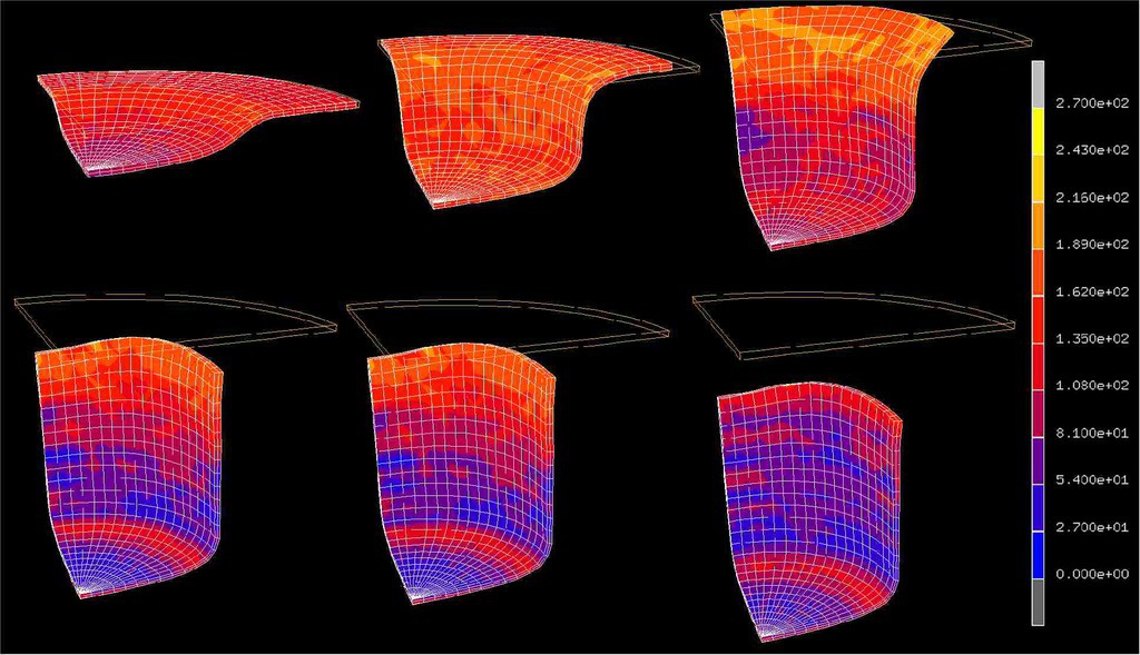
Motivated by this state we present here a numerical study on the influence of crystallographic texture on the earing behavior of a low carbon steel during cup drawing. The simulations are conducted by using the texture component crystal plasticity finite element method which accounts for the full elastic -plastic anisotropy of the material and for the explicit incorporation of texture including texture update. Several important texture components that typically occur in commercial steel sheets were selected for the study. By assigning different spherical scatter widths to them the resulting ear profiles were calculated under consideration of texture evolution. The study reveals that 8, 6, or 4 ears can evolve during cup drawing depending on the starting texture. An increasing number of ears reduces the absolute ear height. The effect of the orientation scatter width (texture sharpness) on the sharpness of the ear profiles was also studied. It was observed that an increase in the orientation scatter of certain texture components entails a drop in ear sharpness while for others the effect is opposite.
Acta Materialia 51 (2003) 1539-1560
Grain-scale micromechanics of polycrystal surfaces during plastic straining
Dierk Raabe, Michael Sachtleber, Hasso Weiland, Georg Scheele, Zisu Zhao
Acta Materialia 51 (2003) 1539 grain mec[...]
PDF-Dokument [1.8 MB]
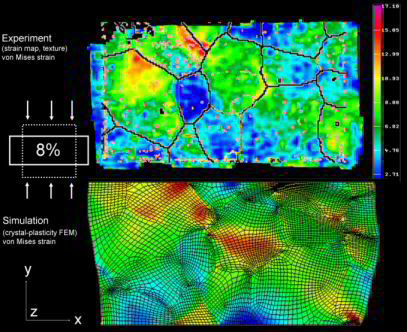
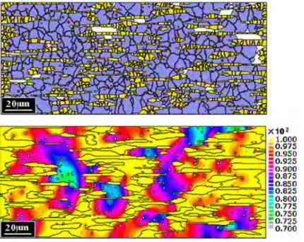
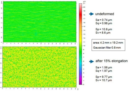
This is a study on grain-scale micromechanics of polycrystal surfaces during plastic straining. We use Al–Mg–Si sheets (alloy AA6022) as model material. The work aims at understanding the relationship between microstrain heterogeneity and surface roughness in plastically strained polycrystals in terms of the surface and through-thickness microstructure. Experiments were conducted on polycrystals with identical composition but different processing and microstructures. We performed tensile and bending tests on sheet samples cut in transverse and rolling directions. We investigated the plastic surface microstrains (photogrametry), surface topography (confocal microscopy), particle distribution (metallography, SEM), microtexture (EBSD), and grain size distribution (EBSD) in the same sample regions. We also conducted in-situ straining experiments where the microtexture, surface topography, and stress–strain behavior were simultaneously determined. The results reveal a relationship between the heterogeneity of plastic surface microstrains, roughness, and microstructure. In particular a correlation could be established between microstrains and banded microtexture components (Cube, Goss, {111}[uvw]).
Grain-scale roughening in homophase alloys can be grouped into orange peel and banding phenomena. The former are characterized by out-of-plane displacement fields (negative or positive), which roughly map the grain shape of the material. The latter are commonly referred to as ridging or roping
phenomena. They occur in the form of banded surface undulations which typically extend along the rolling direction of the material. They have a transverse extension above the grain
size. Grain-scale surface roughening effects have been investigated in various studies, both with respect to the microstructure dependence of wear as well as with
respect to the correlation of surface patterning and microstructure. Most recent studies in this field focused on quantitative microstructure experiments with high lateral resolution.
Special
attention was typically placed on understanding the dependence of surface roughening on grain size, total strain, and crystallographic texture. Early
studies showed that surface roughness increases with the von Mises or respectively through-thickness strain and with the grain size [1–8]. At low
strains both dependencies were often found to be linear. Increasing deviations from a linear relation were observed at medium and large strains. For instance Wilson et al. [5] found a
non-linear dependence of surface roughness on grain size and strain at large plastic strains. Deviations from linearity were also found by Mizuno and Mulki [6]. More recent work
on brass, however, revealed a linear
dependence of surface roughness on both, strain and grain size up to large strains of 0.8 (logarithmic strain) [8]. Also, a close connection was observed between grain-scale surface roughening and crystallographic texture. More precisely, the microtexture, the
misorientation distribution, the two point correlation function, the global texture, as well as
individual crystalline shear and reorientation rates were related to grain-scale roughening [5,9–19]. Due to these studies local crystal orientation analysis plays an ever-increasing role in the investigation of surface micromechanics. An important consequence
of the close relationship between texture and roughening is that surface micromechanics must be regarded as a tensorial and not a scalar
problem [7,20], i.e. the deformation mode has an influence on surface roughness. Vice versa
surface topology was observed to have a significant influence on the forming limits of sheet material. For instance Yamaguchi et al. [20] showed that an
increase in the forming limits of polycrystalline sheet metals could be achieved by removing surface roughness. The experiments were conducted
on balanced biaxial stretching of aluminum sheets and foils. This observation also underlines the close correlation of strain localization, strain hardening,
and surface roughness. Similar observations were made by Jain et al. [7] who studied the correlation of strain hardening, grain size parameters, and surface roughening with respect to
the prediction of biaxial tensile limit strains of two different aluminum sheets with different strain hardening characteristics. An essential detail of this work is that the use
of the average grain thickness as a
measure of the grain size served as an excellent parameter to predict the surface roughness during plastic straining. Mahmudi and Mehdizadeh [8] investigated surface roughening
during plastic straining in uniaxial and equi-biaxial stretching experiments using 70– 30 brass sheets. Their study substantiated for a wide range of parameters a good
correlation between grain size and surface roughness. It was found that the roughness increment was proportional to the applied strain and the grain size of the sheets. Mahmudi
and Mehdizadeh observed for all investigated materials that roughness was more
pronounced in the transverse direction (referring to the coordinate system imposed by rolling) than in the longitudinal direction. The authors concluded
that the non-uniformity of the grain structure, together with the inhomogeneities present in the material, acted as main sources of surface roughening.
Considerable progress towards a more detailed understanding of the micromechanics of grainscale roughening was achieved by the study of Becker [11] who investigated the effects of
strain localization on surface roughness of aluminum sheets employing crystal plasticity finite element simulations. The model accounted for the grain structure near the sheet
surface with the behavior
of the grains being characterized by a constitutive law which accounts for deformation by crystallographic slip and for rotation of the crystal lattice
with deformation. The author found, in addition to the earlier observed linear dependence of surface roughening on strain and grain size, that smallscale
strain localization effects at the sheet surface played a significant role for roughening. From this observation he concluded that factors, which affect
strain localization, such as strain hardening, texture and microstructure homogeneity, also affect surface roughening. His simulations showed for the
first time in a detailed fashion the generation of grain-scale surface patterns induced by the material inhomogeneity inherent in a polycrystal. This study
made clear that even in an otherwise homogeneous portion of material, inhomogeneity generally
enters through the presence of grains with different crystallographic orientation.
Lee et al. [12] investigated the development of grain scale roughening (orange peel) in an aluminum 6022-T4 sheet for automotive application by using interference microscopy and electron back scattering diffraction (EBSD) experiments. No clear relationship was identified between orange peel development and the crystallographic orientation of the surface grains. Brass-oriented grains, {011}k211l (j1=35°, f=45°, j2=0°), tended to be located in the high spots or peaks of the surface of the deformed specimen. Surface height gradients predicted from allowing the surface grains to shear in relaxed constraints mode were weakly correlated with the experimental surface height gradient. Bethke et al. [13] presented a similar detailed microtexture study on ridging phenomena in ferritic stainless steel.
Wittridge and Knutsen [14] investigated the evolution of grain-scale surface roughness during uniaxial tensile deformation, placing particular attention on the development of parallel ridges and valleys in aluminum sheets. Their analysis was based on detailed microstructural characterization techniques including polarized light microscopy, bulk texture determination, and microtexture measurements. The authors interpreted the results in terms of in-plane spatial differences in texture at the sheet surface. They found that colonies of the R texture component, which were embedded in a matrix with predominant Cube orientation, produced differential straining, which eventually entailed strain localization through the specimen thickness and a ribbed profile. This observation confirmed the fact that grain-scale roughening first produces microscopic strain localization at the sheet surface in the incipient stages of plastic straining and eventually macroscopic through-thickness strain localization. In agreement with earlier work along these lines the authors concluded that ridging phenomena could be attributed to texture inhomogeneity. One of the most thorough recent studies in the field was published by Baczynski et al. [15] about roping phenomena in an aluminum 6111 automotive alloy. In this work the authors investigated roping and non-roping materials obtained from two different processing routes. In contrast to earlier work their study showed that both ridges and valleys on the upper and lower surfaces were irregularly distributed in the rolling direction, i.e. they were not in synchrony. Ribbed profiles as well as corrugations were only rarely observed. By using electron back scattering diffraction (EBSD) experiments the authors demonstrated that the spatial distribution of Goss oriented grains were mainly responsible for the roping behavior in the investigated alloy. Furthermore, the authors found that the work hardening rates of roping and non-roping specimens were similar. The anisotropy of fracture elongations in the sheet plane was found to be significantly larger in the roping than in the non-roping material. This observation was interpreted in terms of the strong anisotropy of the Goss texture component in the roping material. Huh and Engler [16] investigated the effects of intermediate annealings on texture and ridging of a 17%Cr ferritic stainless steel. They observed that sheets with weaker through-thickness texture gradients as well as enhanced recrystallization textures were less prone to show pronounced ridging. Similar observations were made by Salsgiver et al. [17]. Engler et al. [18,19] recently presented two detailed reviews on the correlation of ridging and texture in Al–Mg–Si (6xxx) sheet for autobody applications revealing in particular a strong correlation between the orientation density of the Cube orientation and the ridging height. This study investigates correlations between heterogeneous plastic microstrains, microstructure, and both types of intrinsic grain-scale surface effects introduced above (orange peel, ridging/roping). We use a novel experimental approach which is characterized by the joint measurement of accumulated plastic surface microstrains; surface topography; particle distribution; microtexture; and grain size distribution in the same surface areas with high lateral resolution. As model materials we use 6022 aluminum sheets with identical chemical analysis but different microstructures and different surface roughening behavior.
The goal of this study is twofold. First, we aim at an improved basic understanding of the origin of intrinsic microstructural grain-scale roughening effects, focusing both on individual grain and grain-neighbor mechanics (orange peel) as well as on banded grain-cluster mechanics (ridging). Second, we show that the use of photogrametry for the determination of non-homogeneous surface microstrains can serve as an excellent experimental tool for the correlation of microstructure and micromechanical surface phenomena.
The texture component crystal plasticity finite element method
A challenge of integrating constitutive polycrystal plasticity laws into finite element approaches lies in identifying an effective method of mapping a crystallographic texture which represents a large number of grains on the integration points of a finite element mesh. Such an approach must be formulated in a way that still permits texture update in the course of the forming simulation. It is an important condition in that context that crystal plasticity finite element models require a discrete representation of the orientation distribution function at each integration point. For relatively small numbers of grains (less than 103 crystals) the discrete mapping of the texture on the mesh can be achieved by a one-to-one approach, where each Gauss point in the finite element grid is characterized by one crystallographic orientation. This method, however, is not suitable when meshing specimens which contain a much large number of grains such as in a typical steel sheet which is subjected to large scale metal forming operations.
The texture component finite element method is a novel approach in the context described above. It is a technique of approximating an initial orientation distribution function in the form of
discrete sets of symmetrical spherical model functions and in mapping these components on a finite element mesh. Model functions for textures have individual height and individual full width at half
maximum as a measure for the strength and scatter of the texture component they represent.
In the formulation used for this study they have the form of central functions, i.e. their scatter is isotropic in orientation space.
The main task of the concept is to represent sets of spherical Gaussian texture compo-nents on the integration points of a finite element mesh for a crystal plasticity simulation. This procedure
works in two steps.
First, the discrete preferred orientation gc (center orientation, mean orientation) is extracted from each of the texture components and assigned in terms of its respective Euler angle triple , i.e.
in the form of a single rotation matrix, onto each integration point. This step corresponds to the creation of a perfect single crystal.
In the second step, these discrete orientations are re-oriented in such a fashion that their resulting overall distribution reproduces the texture function which was originally prescribed in the form
of a Gaussian texture component. In other words the orientation scatter described initially by a texture component function is in the finite element mesh represented by a systematically re-oriented
set of orientations,
each assigned to one integration point, which reproduces the original spherical scatter prescribed by that component.
This means that the scatter which was originally only given in orientation space is now represented by a distribution both, in real space and in orientation space, i.e. the initial spherical
distribution is transformed into a spherical and lateral distribution. The described allocation and re-orientation procedure is formulated as a weighted sampling Monte Carlo integration scheme in
Euler space.
It is an important detail that the use of the Taylor assumption (or other homogenization methods) locally allows one to map more than one preferred crystallographic orientation on each integration
point and to assign to each of them an individual volume fraction. This means that the procedure of mapping and rotating single orientations in accord with the initial texture component scatter width
is individually conducted for all prescribed components as well as for the random background extracted from initial experimental or theoretical data.
After decomposing and representing the initial texture components as a lateral and spherical single orientation distribution in the mesh, the texture component concept is no longer required in the
further procedure. This is due to the fact that during the subsequent crystal plasticity finite element simulation each individual orientation originally pertaining to one of the texture components
which were initially mapped on the finite element mesh can undergo an individual orientation change as in the conventional crystal plasticity methods.
This means that the texture component method loses its significance during the simulation. In order to avoid confusion one should, therefore, underline that the texture component method is used to
feed textures into finite element simulations on a strict physical and quantitative basis. The components as such, however, are in their original form as compact functions not tracked during the
simulation, but only the individual orientation fractions which compose them. It must also be noted that the orientation points which were originally obtained from the components do not represent
individual grains but portions of an orientation distribution function.
Further details on using the crystal palsticity finite elements method for metal sheet forming simulations can be found here:
Computational Materials Science 34 (2005) 221-234
Crystal plasticity simulation study on the influence of texture on earing in steel
D. Raabe, Y. Wang, F. Roters
Crystal plasticity FE simulation earing [...]
PDF-Dokument [363.8 KB]
 Computational Materials Science 34 (2005) 221-234 Crystal plasticity simulation study on the influence of texture on earing in steel D. Raabe, Y. Wang, F. Roters
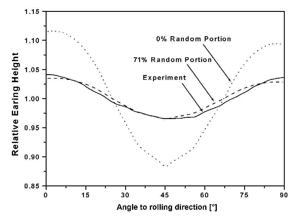
We present a numerical study on the influence of crystallographic texture on the earing behavior of a low carbon steel during cup drawing. The simulations are conducted by using the texture
component crystal plasticity finite element
method which accounts for the full elastic–plastic anisotropy of the material and for the explicit incorporation of texture including texture update. Several important texture components that
typically occur in commercial steel sheets
were selected for the study. By assigning different spherical scatter widths to them the resulting ear profiles were calculated under consideration of texture evolution. The study reveals that
8, 6, or 4 ears can evolve during cup drawing
depending on the starting texture. An increasing number of ears reduces the absolute ear height. The effect of the orientation scatter width (texture sharpness) on the sharpness of the ear
profiles was also studied. It was observed that an increase in the orientation scatter of certain texture components entails a drop in ear sharpness while for others the effect is
opposite.
The shape anisotropy of cup drawn metallic parts is referred to as earing. It is a characteristic phenomenon associated with the crystallographic texture and the resulting elastic–plastic anisotropy of metals [1–16]. Sheet steels usually have pronounced textures which they inherit from the preceding processing steps such as hot rolling, cold rolling, and heat treatment [17–23]. Various concepts exist to introduce texturerelated sheet anisotropy into finite element models
for sheet forming. The initial material anisotropy existing before sheet deformation can be incorporated either through an anisotropic yield surface
function or directly via the incorporation of crystallographic texture models into the finite element codes. The anisotropic yield surface models can be
classified into two groups. The first one comprises empirical and phenomenological anisotropic yield surface equations, such as the equations of Hill from 1948 [24] and 1979 [25],
Hosford [26], Barlat [27], or Barlat and Lian [28] to name but a few important ones. These yield surface functions are
formulated as convex higher-order polynoms, i.e. they take an empirical view at plastic anisotropy. The physical nature of anisotropy can be incorporated
into these concepts for instance by fitting the corresponding polynomial coefficients with the aid of texture-based strain-rate or self-consistent
homogenization methods or with anisotropy parameters obtained from mechanical tests. A detailed overview of this class of yield surface concepts was recently given by Banabic et
al. [29]. The second type of yield surface models is directly formulated as texture-based yield loci [30– 34] the coefficients of which can be directly expressed in terms of the
texture-based mechanical models in conjunction with experimentally determined orientation distributions.
The advantage of yield surface concepts for mechanical anisotropy predictions are relatively short calculation times, when implemented into finite element models, although one must
recall that the measurement of the mechanical anisotropy parameters and the fitting of the anisotropy coefficients must be added to the total time required for a
prediction.
The main disadvantage of the yield surface concept is that they do not consider that the inherited sheet starting textures may evolve further in the course of sheet forming. This
means that reliable anisotropy simulations should incorporate the starting texture as well the gradual update of that texture during deep drawing operations [35]. Some recent
results indeed indicate that the change in crystallographic texture during deep drawing may be relevant for the resulting ear shapes [11,16].
In order to take into account texture evolution during deformation, the crystallographic texture models have been developed. These models can
be roughly classified into three groups, namely, combinations of a Taylor-type strain-rate homogenization model and finite element formulations, the crystal plasticity finite element
model, and texture-function based crystal plasticity finite element models.
The approach of combining a Taylor model with a finite element model was introduced by Gottstein and coworkers [36–39]. In this approach the deformation tensor after each strain
increment is used to prescribe the boundary conditions
for a corresponding Taylor simulation using full constraints or coupled full constraints/grain interaction homogenization model. Each of the finite elements contains its representative
crystallographic texture information in the form of a large set of discrete grain orientations. The Taylor factor calculated from homogenization is fed back into the finite
element simulation as a correction factor for the flow stress in the ensuing simulation step. The particular strength of this method lies in the exact simulation of texture evolution
under intricate boundary conditions. The crystal plasticity finite element models consist
in a direct implementation of crystallographic slip kinematics into finite element models. It was first suggested by Peirce and co-workers [39–42].
Based on their early work a fully-implicit timeintegration scheme was developed by Kalidindi et al. [43] and implemented in commercial finite element software in the form of a
user-defined subroutine. Crystal plasticity finite element models
provide a direct means for updating the material state via integration of the evolution equations for the crystal lattice orientation and the critical resolved
shear stress. The deformation behavior of the grains is at each integration point determined by a crystal plasticity model, which accounts for plastic deformation by crystallographic
slip and for the rotation of the crystal lattice during deformation. Pioneering related studies along these lines have
been published by Mathur and Dawson [44], Smelser and Becker [45], and Beaudoin et al.
[46]. Crystal plasticity finite element models represent elegant tools for detailed simulation studies of texture evolution under realistic boundary conditions. Each integration point can represent one single
orientation or even a large set of discrete grain orientations when combined with an
appropriate homogenization assumption. Although the latter case (mapping of a representative texture on
one integration point) is principally feasible, it entails long calculation times, rendering the
method less practicable for industry-scale applications. For rendering the crystal plasticity finite element models more flexible with respect to the treatment
of large polycrystalline entities Raabe and Roters recently introduced a texture
component crystal plasticity finite element model [47,
48]. The basic idea of this method consists in using a more effective way of describing the texture of macroscopic samples at each integration point,
turning the method into a texture component crystal plasticity finite element method. More details on this approach are given in the ensuing section.
Only few systematic simulation studies were published on the earing behavior of body-centered- cubic steels. For instance, Bacroix and Gilormini [3] presented a detailed work on earing in polycrystalline materials by use of finite-element
simulations. They used a texture-adjusted fourth-order strain-rate potential and its associated normality rule. The coefficients of the potential function were directly obtained
from the texture coefficients. They applied the method successfully to a mild steel. The approach was capable of reproducing six ears for certain textures. Li et al. [33,38]
predicted the earing behavior of cup drawn
IF (interstitial free) steel sheets by use of a texture-based plastic potential formulation. The group of Nakamachi et al. [49,50] used an elastic–viscoplastic
finite element method to simulate the six and four ears of drawn cups of body centered cubic polycrystals. In order to achieve this goal they used a large number of integration points
in conjunction with a crystal plasticity finite element formulation. Each rotation matrix mapped at an integration point was assumed to represent one grain. The crystallites could
hence rotate individually upon mechanical loading. The sheet metal forming simulations of Nakamachi et al. [49,50] were not only used to predict the earing behavior but also to
assess texture effects on strain localization and failure. The authors reported that {111}- huvwi orientations (c-fiber texture) are favorable while the {hkl}h001i texture components
where less favorable for sheet formability of steels.
These studies provide in part excellent insight into the relationship between the initial crystallographic texture of steel sheets before cup drawing and the resulting ear profiles
after deformation. Building on these observations the present study aims at pushing this effort a step further by, first, rigorously incorporating texture update into
the simulations according to the crystal plasticity scheme, second, by a systematic variation of the relevant texture components typically occurring in body-centered-cubic steels
[22,23], and third,
by systematically varying the orientational scatter width of those texture components. The simulations are conducted by using the texture component
crystal plasticity finite element model. After an introduction to this method and to the model set-up we simulate the individual ear profiles resulting from some typical texture
components of body-centered-cubic polycrystals. Subsequently, we discuss the effects of these texture components on the observed ear profiles and also the effects of changes in
the scatter width of these textures on the ear profile.
Journal of Materials Processing Technology 183 (2007) 169–175
A texture component crystal plasticity finite element method (TCCP-FEM) is used for the simulation of the deep drawing process of sheet
PROTEC10240-deep-drawing-simulation.pdf
PDF-Dokument [870.1 KB]
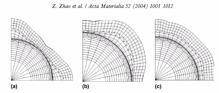
Acta Materialia 52 (2004) 1003-1012
Z. Zhao, W. Mao, F. Roters, D. Raabe
A texture optimization study for minimum earing in aluminium by use of a texture component crystal plasticity finite element method
The influence of discrete texture components and combinations of them on the earing behavior of aluminium during cup drawing was systematically investigated.
Acta Materialia 52 (2004) 1003 Aluminum [...]
PDF-Dokument [415.8 KB]
 Acta Materialia 52 (2004) 1003 Z. Zhao, W. Mao, F. Roters, D. Raabe A texture optimization study for minimum earing in aluminium by use of a texture component crystal plasticity finite element method
 Acta Materialia 52 (2004) 1003 Z. Zhao, W. Mao, F. Roters, D. Raabe A texture optimization study for minimum earing in aluminium by use of a texture component crystal plasticity finite element method
Engineering polycrystalline materials often exhibit significant elastic–plastic anisotropy that can be attributed to the presence of crystallographic texture. In the
early industrial practice texture was long a property of polycrystals which was simply inherited from the preceding processing steps without conducting particular
anisotropy optimization. This means that textures were known as an inevitable side-effect of materials processing which was hard to avoid and
often accepted as it was. In contrast, modern industrial process design gradually aims at optimizing microstructures and properties during production, i.e., its goal consists in
exploiting metallurgical mechanisms such as crystal plasticity, recrystallization, grain growth, and phase transformation for the design of well tailored
crystallographic textures with respect to certain desired anisotropy properties of the final product.
A typical example is the development of {1 1 1} uvw textures of soft interstitial-free steels (IF steels) which are optimized with respect to sheet forming. In these body centered cubic (bcc)
materials the {1 1 1} 11 2 and {1 1 1} 1 10 texture components each reveal a sixfold symmetry of the shape change with respect to the sheet surface, due to the symmetry of the active
crystallographic slip dyads. In case that a complete fiber texture exists with a common 111 crystal axis parallel to the sheet surface a very high planar-through-thickness anisotropy (r-value or
Lankford-value) and a vanishing in-plane anisotropy (Delta-r-value) exists. The most recent phase in the advancement of quantitative texture and anisotropy engineering consists in the introduction of
inverse texture simulation methods. Such approaches are designed for the physically based tailoring of optimum textures for final products under consideration of prescribed processing and
materials conditions on an inverse basis. This means that variational texture optimization can nowadays be conducted in a way to match some desired final anisotropy and can help to
identify beneficial corresponding processing parameters. This amounts to a tenet change in the sense that the process should no longer determine the textures but the desired textures should
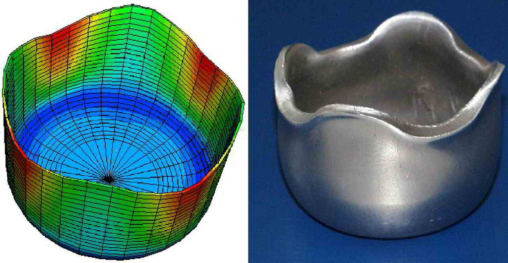
determine the process. Plastic anisotropy during deep drawing may entail the formation of uneven rims of the drawn product, usually referred to as earing. One important consequence of that is –
besides the irregular shape of the drawn specimen – an inhomogeneous distribution of the mechanical properties and of the wall thickness due to volume conservation and the kinematically
necessary strain rate variation. The trivial solution for the control and minimization of earing would be the presence of a random crystallographic texture prior to loading. However, such a supposed
obvious approach is prevented due to two reasons. First, random starting textures do generally not remain random when the material is plastically deformed. This applies in particular to sheet forming
operations. Second, complete spherical and topological randomization of textures is very difficult. Most metallurgical and mechanical processes promote rather reduce orientation distributions.
This applies in particular to most face centered cubic (fcc) metals, in particular to those without bulk phase transformation during forming such as aluminium. Therefore, a more practical approach
for reducing shape anisotropy lies in combining the texture components constituting the initial sheet in such a way that the resulting ear profile – accounting also for texture changes during
forming – can be minimized owing to the mutual compensation of the shape anisotropy contributions introduced by the individual texture components during forming. The present work pursues this
approach.We apply an inverse texture simulation method to the optimization of the shape anisotropy occurring during cup drawing of fcc polycrystals with a high stacking fault energy containing a
large number of grains (large meaning ngrains > 104 as typically present in engineering sheet material). As a typical sample material we choose the constitutive behavior of aluminium. The rolling
texture in such alloys is primarily composed of the S orientation, {1 2 3} 63 4, the Brass orientation, {1 1 0} 1 12, and the Copper orientation {1 1 2} 11 1. These texture components
promote earing essentially at 45 /135 with respect to the rolling direction. Annealing textures which may contain the Cube orientation, {1 0 0} 001, and also some Goss orientation, {1 1 0}
001, also promote pronounced earing, namely, at the 0/90 directions for the Cube orientation and the Goss orientation [1–9]. A useful approach, therefore, might consist in creating a
sheet material with a low ear ratio by a suitable combination of crystals with an orientation that results in 45 /135 ears and those that produce 0/90 ears [1,2]. In order to
identify a theoretical solution for minimum shape anisotropy after deep drawing as a result of a suited combination of these orientations we employ a texture component crystal plasticity finite
element method [10–14]. The use of this new simulation method offers five main advantages. First, the approach allows one to conduct predictions of earing including all texture changes occurring
during deep drawing. Second, the method is quantitative. Third, the approach allows us to also simulate wall thickness and heterogeneity of the mechanical properties after deformation. Fourth,
the predictions include the optimization of the spherical scatter width of texture components. Fifth, the methods allows us to directly feed in the starting textures. The purpose of this paper
consists first, in deriving
the ideal texture composition for minimum earing in fcc metals with high stacking fault energy in a quantitative fashion and second, to establish the texture component crystal plasticity finite
element method as a pertinent inverse materials engineering tool for anisotropy optimization. After an introduction to the new texture component crystal plasticity finite
element method (TCCP-FEM) and to the model set-up we simulate the individual earing profiles of some main texture components of rolled and annealed aluminum. Subsequently, we present for two of
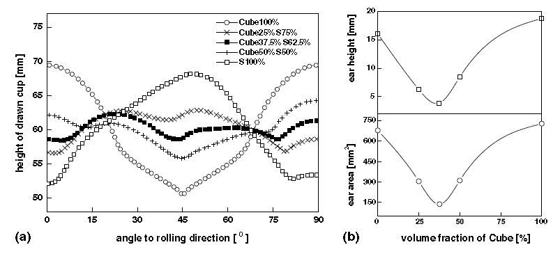
them, namely, for the Cube and the S orientation, a set of simulations which aims at optimizing their volume ratio for obtaining minimum earing including the discussion of the influence of the
spherical scatter width of the texture components on the ear profile.
More specific in this paper the influence of discrete texture components and combinations of them on the earing behavior of aluminium during cup drawing was systematically investigated using the texture component crystal plasticity finite element method. Several common texture components and their combinations were selected and the resulting ear profiles were calculated under consideration of texture changes. The spherical scatter width of the components was also taken into account as an optimization parameter. The study reveals that the ear height and profile can be minimized by an optimized combination of certain texture components including their scatter width. A solution for minimum earing of cup drawn aluminium was obtained for a combination of the S and the Cube texture components with 15° spherical scatter width.
Materials Science and Engineering A 488 (2008) 482–490
A texture component crystal plasticity finite element method (TCCP-FEM) is used for the simulation of cup drawing of a ferritic stainless steel
Materials Science and Engineering A 488 [...]
PDF-Dokument [1.5 MB]
Ferritic stainless steels form a prominent group of construction and functional materials owing to their favorable combination of mechanical properties and corrosion resistance [1].
An important problem in the industrial processing
and the final properties of these materials is the inhomogeneity of the texture through the thickness of the cold rolled and recrystallized sheets [2–6]. Detailed experimental texture
studies have shown that these pronounced through-thickness texture gradients are due to texture inheritance from the preceding hot rolling procedure [7– 19]. Factors such as roll-gap
geometry, including the geometrical changes during a rolling pass, friction between the roll and the sheet contact surface, and the temperature gradients during hot rolling can give
rise to non-homogeneous through-thickness strain fields and, as a consequence, to different hot rolling textures in different through-thickness layers [2,5,7] entailing also
inhomogeneous strength and deep drawing properties of the final product. Furthermore, through-thickness texture gradients
have been linked to the phenomenon of ridging in ferritic stainless steels [20–30]. Corresponding correlation studies have revealed that sheets with stronger texture gradients are more
prone to showing pronounced ridging. Thin strip casting as opposed to conventional hot rolling before cold rolling and final recrystallization annealing has turned out to be an
alternative processing route which entails superior sheet properties including negligible through-thickness
and smaller in-plane texture gradients when compared to conventionally processed material [31–36]. Owing to these different aspects associated with texture inheritance in ferritic
stainless steels a reliable texture simulation of forming processes of ferritic steels which takes into account through-thickness texture gradients of the hot band sheet is an
essential challenge when optimizing these materials. The aim of this study, therefore, is improving the prediction of the texture evolution during cold rolling of hot rolled
ferritic stainless steel (X6Cr17) using the texture component crystal plasticity finite element method (TCCP-FEM) with 24 slip systems. This method works by using spherical orientation
components for the texture approximation instead of sets of single orientations. More details on that are given in the ensuing section and in Refs. [37–45]. The measured texture of a
hot band steel sheet, fitted by using the texture component method, was used as starting texture for the FE calculation. In order to take the initial texture heterogeneity of the hot
band sheet into account in the simulation, a simplified through-thickness texture gradient was mapped in the FE model. The simulation results are compared to experimental data and to
earlier literature data of through-thickness texture gradients observed in rolled sheets of ferritic stainless steels
Hence in this work we use a texture component crystal plasticity finite element method for the simulation of plane strain compression (maximum thickness
reduction 95%) of a ferritic stainless steel (X6Cr17, AISI 430, 1.4016). The method incorporates the graded hot band texture of the
starting material and predicts the development of the orientation distribution during forming in t
Computational Materials Science 46 (2009) 383-392
Virtual material testing for stamping simulations based on polycrystal plasticity
M. Kraska, M. Doig, D. Tikhomirov, D. Raabe, F. Roters
Computational Materials Science 46 (2009[...]
PDF-Dokument [2.5 MB]
 Computational Materials Science 46 (2009) 383-392 Virtual material testing for stamping simulations based on polycrystal plasticity M. Kraska, M. Doig, D. Tikhomirov, D. Raabe, F. Roters
 Computational Materials Science 46 (2009) 383-392 Virtual material testing for stamping simulations based on polycrystal plasticity M. Kraska, M. Doig, D. Tikhomirov, D. Raabe, F. Roters
The highly competitive automotive market demands for lightweight and safe vehicles. These requirements can be met using, for example, high strength multiphase steels. Along with the positive
service properties like higher strength and energy absorption during crash these steels tend to higher springback after forming. The modern forming technology is aimed at early compensation of
springback by corresponding modification of the tool geometry Roll et al. [20]. In order to comply with shape tolerances, iterative tool modifications are required. Reliable simulation tools with
exact springback prediction are required which can considerably accelerate the stamping tool design and optimization process and reduce the time before the start of production.
Various factors have a significant impact on springback simulation results. Tool shape (drawing radii), discretization (mesh density, element types), contact and friction between sheet
and stamping tool as well as the elastoplastic sheet material behavior during the process influence the resulting springback. In this paper we restrict our attention to the latter aspect, namely
material modeling. The demands of industrial applicability of springback simulation comprise reliable stress prediction, handling of multiaxial loads and load direction change, accounting for sheet
orthotropy as well as isotropic and kinematic hardening phenomena (Bauschinger effect).
Commercial software packages offer a variety of empirical constitutive laws for stamping simulations, a comprehensive overview of these models can be found in Banabic et al. [4]. In the most cases
the constitutive laws by Hill [9,10] and Barlat (Barlat et al. [5], Barlat and Lian [6]) are used for stamping simulations. The evolution of material properties is usually modeled by isotropic and/or
kinematic hardening with linear (Prager [18] type) or nonlinear (Ziegler [24] or Armstrong and Frederick [1] type) evolution of back stress. The empirical laws are well suited for industrial stamping
simulation, particularly because of relatively short computation times and the macroscopic character of the most model parameters which normally can be identified from standard testing
procedures.
However, sometimes, as practice shows, a reliable prediction of springback after die opening cannot be achieved. One of the drawbacks of the most empirical formulations is the insufficient
consideration of changing material anisotropy due to microstructure evolution. In this sense, microstructural models can help to better identify the macroscopic properties of the empirical model.
Microstructural models based on texture allow the user to include more physics associated with crystalline anisotropy, although they lead to longer computation times. In this article we pay attention
to the crystallographic anisotropy of polycrystalline materials rather than morphological microstructure anisotropy. The physical background of crystallographic anisotropy is the crystalline
arrangement of atoms. Each grain of the metallic material has a different crystallographic orientation, shape and volume fraction. The discrete nature of crystallographic slip along densely packed
lattice directions on preferred slip planes also contributes to the overall anisotropic response of material. Moreover, individual crystals rotate and interact during forming. This leads to strong
heterogeneity of strains and stresses. Texture and anisotropy gradually change, even under constant strain path condition. The presented approach demonstrates the use of performing of various virtual
tests on a representative volume element (RVE) using the crystal plasticity model to identify the macroscopic yield behavior of the material and to extract hereof parameters for industrial
stamping simulations.
The goal of this article is to present a virtual technique to determine the material parameters characterizing the ductile metal behavior (yield locus and r-values). It enables to considerably reduce
the experimental expenses. That is of particular importance for the industrial goals, because in this way both cost and time savings can be achieved. The presented model is more complex than a
conventional Taylor model but is limited in order to get the plausible results in a limited time. In this model the simplest approximation of a grain via one finite element is used. In this case
the grain morphology is not taken in account, however, this is the easiest way to keep the model complexity within certain bounds. Extensions of this model to mutually opposed limit states –
discretisation of a single grain with many finite elements or assuming many grains (orientations) in each integration point – are possible but the experimental and numerical complexity to adjust the
model will grow.
The influence of the discretization on strength and stiffness of the aggregate has been investigated previously in Kraska [12]. The influence of the number of elements per grain has been
separated from the stiffening influence of different boundary conditions (periodic boundary conditions versus suppressed local fluctuations at the RVE boundary). It was found that for moderate
numbers of
elements per grain, convergence cannot be expected (up to 320 constant strain elements per grain have been considered, this corresponds to 4 4 4 cubes per grain). Thus, the choice of the
discretization level is always a trade-off between good texture representation (number of grains) and good representation of local strain fluctuations (non-homogeneities, requiring fine meshes
on
grain level). Obviously, a pragmatic choice has to be made based on the acceptable computational costs. This choice has to be kept from the initial slip system calibration based on tensile
tests throughout all virtual testing. Different levels of grain discretization provide different slip system calibrations. However, as long as the aggregate is able to represent the main
features of the deformation induced texture, reasonable extrapolation can be expected. Even with coarse discretization, the model is still superior to simple mixing rules (Taylor model); because the
induced textures are more realistic and local strain fluctuations are still allowed for. This paper is organized as follows. After a brief overview of the technique of the crystal plasticity FEM the
concept of virtual material testing using representative volume element is described. Virtual tests enable to replace the costly numerous uniaxial tensile experiments and give the opportunity to
investigate those stress and strain states which are not a standard in the material testing practice like biaxial tensile, compressive or shear tests. The application of the crystal plasticity
FEM for the virtual testing
is demonstrated for DC04 and H320LA steels. The ability of the model to simulate the rolling texture of steel is shown. The effects of different boundary conditions of RVE and element types on
the nominal stresses and Lankford parameters are numerically investigated. The pronounced Bauschinger effect for texture-based RVE is demonstrated by cyclic uniaxial tests. As a potential
application a complex part has been simulated using the Vegter yield locus in
PAMSTAMP 2G. This model interpolates over many tests, which in the present case have been run virtually. The perspectives and limitations of the applied approach are discussed
In summary this article deasl with an approach to virtual material testing for stamping simulations based on polycrystal plasticity.
In the modern practice of stamping simulation of complex industrial parts the prediction of springback still lacks accuracy. In commercial software packages various empirical constitutive laws for
stamping are available. Limited to simple empirical models for material anisotropy they do not take into account in a full manner the effects of microstructure and its evolution during the
deformation process. The crystal plasticity finite element method bridges the gap between the polycrystalline texture and macroscopic mechanical properties that opens the way for more profound
consideration of metal anisotropy in the stamping process simulation. In this paper the application of crystal plasticity FEM within the concept of virtual material testing with a representative
volume element (RVE) is demonstrated. Using virtual tests it becomes possible, for example, to determine the actual shape of the yield locus and Lankford parameters and to use this information
to calibrate empirical constitutive models. Along with standard uniaxial tensile tests other strain paths can be investigated like biaxial tensile, compressive or shear tests. The application of the
crystal plasticity FEM for the virtual testing is demonstrated for DC04 and H320LA steel grades. The parameters of the Vegter yield locus are calibrated and the use case demonstration is completed by
simulation of a typical industrial part in PAMSTAMP 2G.
JOM • April 2011 (TMS)
Aiming for an integrated approach to computational materials engineering in an industrial context poses big challenges in the development of suitable materials descriptions f
2011-overview-microstructure-models-JOM.[...]
PDF-Dokument [1.5 MB]
 Crystal plasticity finite element simulation of sheet forming
Advanced Engineering Materials
Volume 4, Issue 4, pages 169–180, April, 2002
Concepts for Integrating Plastic Anisotropy into Metal Forming Simulations
D. Raabe, P. Klose, B. Engl, K.-P. Imlau, F. Friedel and F. Roters
Advanced Engineering Materials 4 (2002) [...]
PDF-Dokument [621.9 KB]
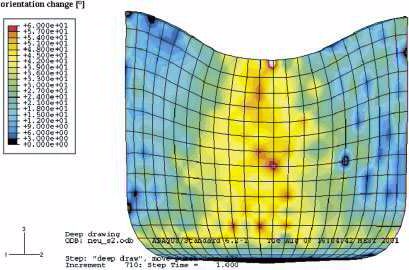 Advanced Engineering Materials Volume 4, Issue 4, pages 169–180, April, 2002 Concepts for Integrating Plastic Anisotropy into Metal Forming Simulations
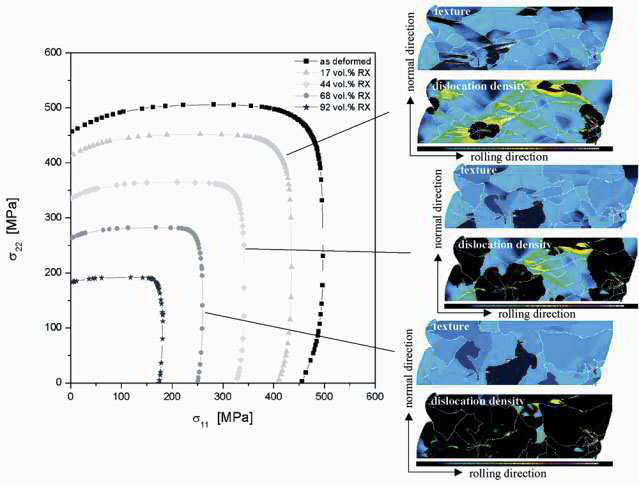 Advanced Engineering Materials Volume 4, Issue 4, pages 169–180, April, 2002 Concepts for Integrating Plastic Anisotropy into Metal Forming Simulations
Modern metal forming and crash simulations are usually based on the finite element method. Aims of such simulations are typically the prediction of the material shape, failure, and mechanical
properties during deformation. Further goals lie in the computer assisted lay-out of manufacturing tools used for
intricate processing steps. Any such simulation requires that the material under investigation is specified in terms of its respective constitutive behavior. Modern finite element simulations
typically use three sets of material input data, covering hardening, forming limits, and anisotropy. This short article is about the latter aspect. It reviews different empirical and physically
based concepts for the
integration of the elastic-plastic anisotropy into metal forming finite element simulations. Particular pronunciation is placed on the discussion of the crystallographic anisotropy of
polycrystalline material rather than on aspects associated with topological or morphological microstructure anisotropy. The
reviewed anisotropy concepts are empirical yield surface approximations, yield surface formulations based on crystallographic homogenization theory, combinations of finite element and
homogenization approaches, the crystal plasticity finite element method, and the recently introduced texture component
crystal plasticity finite element method. The paper presents the basic physical approaches behind the different methods and discusses engineering aspects such as scalability, flexibility, and
texture update in the course of a forming simulation.
The advance of modern well-tailored and optimized materials nowadays provides a huge and steadily-growing application spectrum to customers of formed products. Well established examples are the introduction of high-strength
multi-phase steels or 6xxx series aluminum alloys for the automotive industry. The high demands with respect to mechanical properties and surface appearance faced by these materials
in the course of metal forming increasingly requires adequate quantitative characterization measures to build a
bridge between producers and product designers. Modern approaches for conducting simulations of plastic deformation are usually based on solving large sets of differential equations
associated with a well posed forming problem by use of non-linear finite element methods. Primary objectives of such simulations are the prediction of the material shape after forming, in
particular the thickness distribution; the minimization of material failure in conjunction with the optimization of material flow during forming; and the calculation of the final mechanical
properties of the formed sample. Further related essential
applications are in the fields of optimizing tool designs, predicting pressing forces, and simulating the final surface appearance of the part. The latter aspect involves
both, macroscopic (e.g., wrinkling) as well as microstructural (e.g., ridging, orange peel) mechanisms for changes in surface quality during forming.
Rendering continuum-type metal forming simulations scientifically sound, predictive at the microstructure scale, in good accord with experiment, and at the same time economically
rewarding requires that the involved materials are properly specified in terms of their respective constitutive behavior. For this purpose modern finite element simulations typically
employ three sets of
material input data, covering hardening, forming limits, and anisotropy. The current article deals with the latter aspect. It reviews both, empirical and physically based concepts
for the integration of the elastic-plastic anisotropy
into metal forming finite element simulations. Particular pronunciation is placed on the discussion of the crystallographic anisotropy of polycrystalline material rather than on
aspects associated with topological or morphological microstructure anisotropy. The various anisotropy concepts which will be
reviewed in the following are empirical yield surface approximations, yield surface formulations based on crystallographic homogenization theory, combinations of finite element
and homogenization approaches, the crystal plasticity finite ele- ment method, and the recently introduced texture component
crystal plasticity finite element method. By providing a survey on the advantages and disadvantages of the various anisotropy concepts the article takes an
effort to present both, the present state of the art in the industrial practice as well as advanced approaches which allow the user to include more of the physics associated with
crystalline anisotropy. The present state in anisotropy engineering is naturally different between industrial applications and basic
science. The use of empirical or semi-empirical polynomials for yield surface approximations is the standard procedure in the industrial practice whereas the various crystal
plasticity finite element methods gradually become a standard in the basic materials sciences. The importance of empirical approaches in the industrial practice is due to the fact that
they provide short computation times, allow for simple mechanical input data, and are flexible with respect to additional fit points obtained by texture information. An important weakness
of empirical approaches lies in the absence of texture update. The prevalence of the crystal plasticity finite element method in basic research is due to its physical basis and
the incorporation of texture changes. The major drawback of the crystal plasticity approaches are the long calculation times which presently profoundly exceed those obtained by use of
the yield surface. An improvement in speed of the
crystal plasticity methods is attained by the recent introduction of the texture component crystal plasticity finite element method which exceeds the computation times of yield
surface calculations only by a factor of 15-25.
The paper has the following plan: First, we give a brief introduction to the physical origin of elastic-plastic crystallographic anisotropy. Second, we present the basic approaches behind the
different anisotropy concepts and discuss aspects such as scalability, flexibility, and texture update in the course of forming simulation.
We discuss methods to map crystallographic textures in crystal plasticity finite element simulations.
Texture-Component-Crystal-Plasticity-FEM[...]
PDF-Dokument [841.7 KB]
Acta Materialia 58 (2010) 1152–1211
Overview paper
Crystal Plasticity Finite Element Overvi[...]
PDF-Dokument [6.3 MB]