
Metastability of High-Strength Steels
Based on: B. Sun, A. Kwiatkowski da Silva, Y. Wu, Y. Ma, H. Chen, C. Scott, D. Ponge, D. Raabe, “Physical metallurgy of medium-Mn advanced high-strength steels”, International Materials Reviews 68(7): 786–824, 2023.
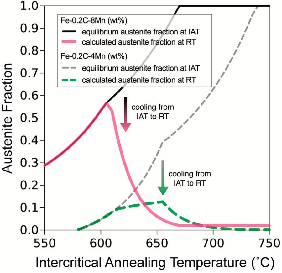 Figure 1. Calculated austenite fraction at the intercritical annealing temperature (IAT) and retained austenite fraction after quenching to room temperature (RT) for two MMnS compositions (Fe-0.2C-8Mn and Fe-0.2C-4Mn, in wt-%). The calculation follows Ref
Introduction: a class of steels built on metastability
Steels do not have to sit at equilibrium to be strong, and in one of the fastest-growing classes of structural steels this is deliberately avoided. Medium-Mn steels (MMnS), Fe-based alloys with 3 to 12 wt% Mn, occupy the composition gap between first-generation low-Mn steels (below 3 wt%) and second-generation high-Mn steels (above 13 wt%). Introduced as a composition-efficient TRIP steel in the 1970s, the class has now emerged as an independent material family, generally regarded as the leading candidate for the third generation of advanced high-strength steels (AHSS). The driving idea is metastability: a substantial fraction of austenite is retained at room temperature in a thermodynamically metastable state and is programmed to transform to martensite under mechanical load. That single design decision activates nearly all known strengthening and strain-hardening mechanisms — solid-solution strengthening, interface strengthening, precipitation strengthening, dislocation strengthening, transformation-induced plasticity (TRIP), twinning-induced plasticity (TWIP), dynamic strain aging, and multiphase composite hardening — within a single, lean alloy system. The result is a strength–ductility synergy reaching tensile strengths of about 2400 MPa, total elongations of about 95%, and strength-times-elongation products of 80 GPa%.
What makes the class unusual is that it offers four independently tunable dimensions of complexity: (a) chemical composition and inter-phase solute partitioning; (b) microstructural variety in the phases and constituents — austenite, ferrite, martensite, bainite, pearlite and carbides — including their size, morphology, distribution and percolation; (c) microscopic solute enrichment at lattice defects, which can be used for deliberate segregation functionalization; and (d) the mechanical stability design of the austenite and the dislocation and athermal mechanisms it activates during deformation. The review by Sun, Raabe and co-workers examines how the thermodynamics, kinetics and micromechanics of this metastability work, and where the material is still short of full understanding and industrial readiness.
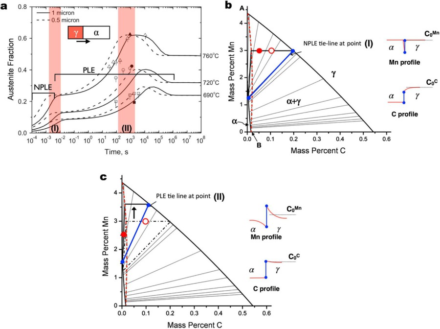 Figure 2. (a) Austenite volume fraction as a function of time for a 0.1C-3Mn-1.5Si (wt-%) steel simulated by using DICTRA for different temperatures, with different growth stages ranging from NPLE boundary conditions to PLE boundary conditions, as highlig

Steels with medium manganese (Mn) content (3∼12 wt-%) have emerged as a new alloy class and received considerable attention during the last decade. The microstructure and mechanical response of such alloys show signifi cant diff erences from those of established steel grades, especially pertaining to the microstructural variety that can be tuned and the associated micromechanisms activated during deformation. The interplay and tuning opportunities between composition and the many microstructural features allow to trigger almost all known strengthening and strain-hardening mechanisms, enabling excellent strength-ductility synergy, at relatively lean alloy content. Previous investigations have revealed a high degree of microstructure and deformation complexity in such steels, but the und
Physical metallurgy of medium-Mn advance[...]
PDF-Dokument [9.1 MB]
Strength through phase weakness: Alloying the metastable austenite phase
Manganese is the central element. Each 1 wt% Mn added to austenite lowers the martensite start temperature by roughly 30–40 °C and the Md30 temperature by about 10 °C, so that an additional 2–3 wt% Mn can raise the retained-austenite fraction by around 20 vol.-%. Mn also lowers the Ae1 and Ae3 temperatures, shifting the austenite–ferrite intercritical window to lower temperatures. Two further properties of Mn are decisive for the whole class. First, the stacking fault energy (SFE) of austenite in binary Fe–Mn alloys varies parabolically with composition, with a minimum at 10–16 wt% Mn — precisely the range the austenite phase reaches after partitioning in most medium-Mn alloys. SFE, and hence the deformation mode of the metastable austenite (slip, twinning, transformation), is therefore a quantity that can be dialled in by composition and partitioning. Second, Mn segregates strongly to lattice defects while diffusing slowly inside austenite; this slow Mn diffusion is actually exploited as a design principle for patterning local Mn enrichment (Section 5).
Carbon, in addition to stabilizing austenite, is the strongest interstitial hardener available: per 1 wt% C, a hardening of several thousand MPa is possible in ferrite and α′-martensite. It also raises the SFE of the austenite by 2.5–4 mJ/m² per 0.1 wt%, directly steering the deformation mode of the metastable phase, and its coupling to dislocations governs the discontinuous yielding and Portevin–Le Chatelier (PLC) serrations.
Aluminium and silicon both stabilize ferrite and widen the austenite–ferrite intercritical field, and Al in addition reduces the mass density by about 1.3% per 1 wt%, which is why “lightweight” medium-Mn grades contain up to 10 wt% Al. Al raises the SFE of the austenite by about 8.5 mJ/m² per 1 wt% and suppresses deformation-induced ε-martensite. Si is the more effective solid-solution strengthener (about 120 MPa per 1 wt% for ferrite and up to about 65 MPa per 1 wt% for austenite) and lowers the SFE by 2–3.5 mJ/m² per 1 wt%. One caution: both Al and Si promote B2 and D0₃ ordering inside ferrite, which produces dissociated superlattice dislocations, suppresses cross-slip, and raises the stress concentrations that drive cracking.
Micro-alloying elements (V, Nb, Ti) add precipitation hardening and, in some applications, hydrogen-trapping carbides; co-doping of Cu and Ni introduces coherent Cu-rich nanosized precipitates; Cr improves oxidation and corrosion resistance, including for press-hardened grades.
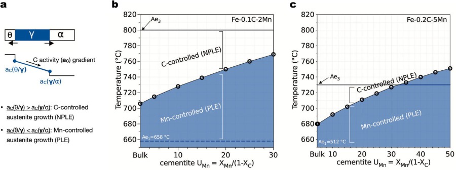 Figure 3. (a) Schematic illustrations of austenite (γ) growing from cementite (θ)/ferrite (α) interface. By comparing the C activity at the θ/γ interface and γ/α interface, this can be used to determine whether a positive C activity gradient in austenite
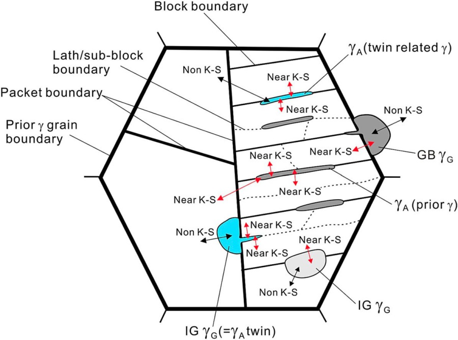 Figure 4. Schematics of austenite growth at different nucleation sites in lath martensite and the evolved OR with the neighbouring phase and the developed austenite morphology, in which GB γG represents grain boundary (GB) austenite.
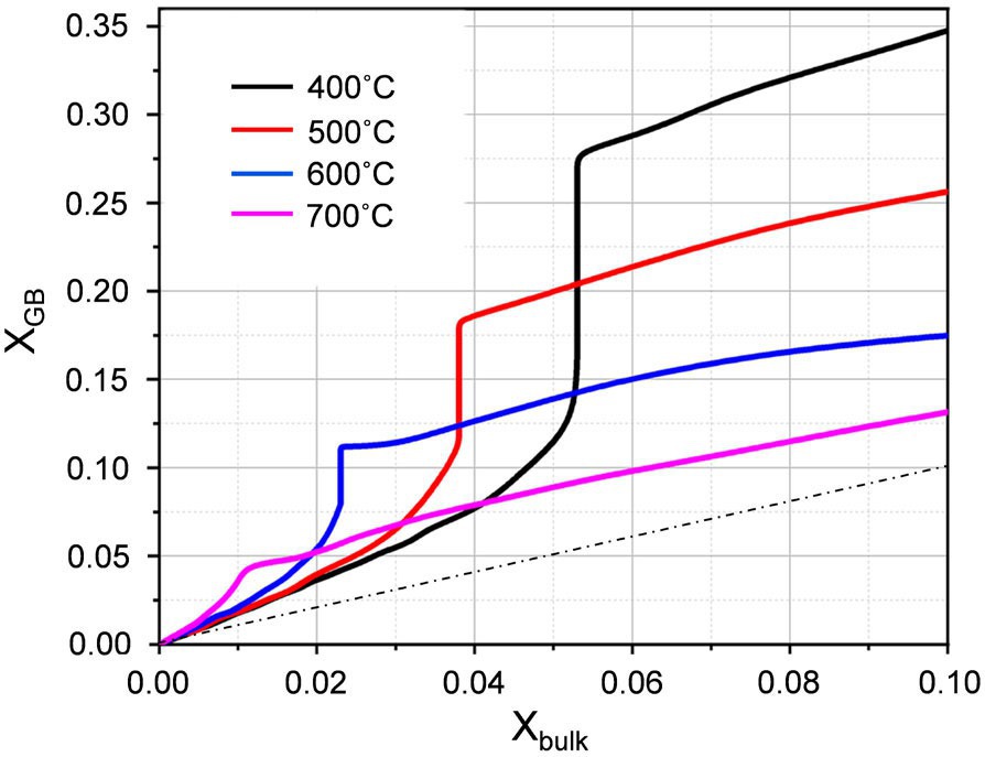 Figure 5. Segregation isotherms at different temperatures assuming metastable local diffusional equilibrium between the BCC bulk phase (coordination number z = 8) and the grain boundary (reduced coordination number z = 6).
Thermodynamics and kinetics of metastable austenite
The fraction of metastable austenite retained at room temperature is first set by annealing thermodynamics. Equilibrium calculations for two representative compositions (Fig. 1) show the retained-austenite fraction first increasing and then decreasing with intercritical annealing temperature: austenite formed at higher temperature is less enriched in C and Mn, and a part of it transforms to martensite on quenching. Real alloys, however, rarely reach these limits, because growth kinetics and nucleation control how much austenite forms, how much solute it picks up, and where.
In the moving-boundary picture of austenite growth from ferrite, the interfacial boundary condition itself evolves with time (Fig. 2). Growth starts as a fast, carbon-diffusion-controlled stage under negligible-partitioning local equilibrium (NPLE), then transitions to an Mn-diffusion-controlled stage under partitioning local equilibrium (PLE), the interfacial tie-line shifting towards the maximum interfacial Mn content in austenite. For most MMnS compositions this first NPLE stage is not observed experimentally at typical intercritical annealing conditions, because interfacial dissipation and — above all — carbides in the starting microstructure change the problem. Where Mn-enriched cementite is present, austenite nucleating at cementite/ferrite interfaces is Mn-diffusion-controlled over much of the intercritical range (Fig. 3), consistent with the slow reversion kinetics commonly measured in carbide-containing medium-Mn steels.
Nucleation is at least as important as growth. In quenched lath martensite, austenite forms at lath, block, sub-block and prior-austenite grain boundaries, typically with a near Kurdjumov–Sachs orientation relationship to the martensite — the so-called austenite memory effect (Fig. 4). The resulting lamellar reverted austenite grows sluggishly, attributed to the low mobility of the semicoherent K–S interface, although the quantitative relation between interfacial crystallography and boundary mobility has not yet been established.
At the atomic scale, metastability is prepared by segregation. The positive excess enthalpy of mixing of Fe and Mn drives Mn to low-coordination environments — grain boundaries and dislocations — in a process well described by bond-breaking (Gibbs adsorption) thermodynamics (Fig. 5). Atom-probe tomography of a Fe–9Mn model alloy shows Mn-decorated boundaries whose compositional fluctuations resemble a confined spinodal decomposition, and which act as non-classical precursors for austenite nucleation (Fig. 6). Co-segregated carbon lowers the local activity of Mn, further enhances Mn segregation, and promotes the first austenite embryo when the carbon content is too low for carbide nucleation.
Kinetic decoupling of the fast-diffusing C from the slow-diffusing Mn is itself a design tool. Mn bands inherited from Scheil-type solidification create a spectrum of local austenite stabilities and a correspondingly heterogeneous TRIP effect. A pearlitic starting structure with Mn-enriched cementite, austenitized fast enough that Mn cannot diffuse, leaves alternating Mn-rich and Mn-lean austenite that on quenching becomes a nanolamellar mixture of stable austenite and martensite (Fig. 7). Two-step treatments exploiting the temperature dependence of the interfacial tie-line produce Mn-rich core–shell austenite, in which the Mn-rich shell suppresses martensite nucleation at the Mn-lean core.
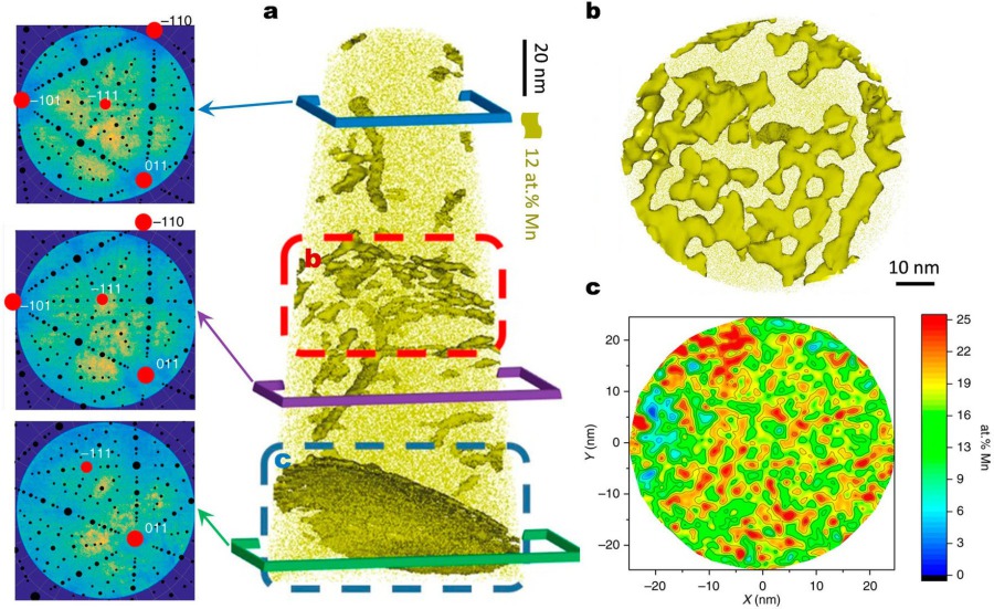 Figure 6. APT analysis of grain boundaries decorated with Mn after 6 h at 450°C. (a) The 12.5 at-% Mn iso-concentration surfaces (12.5 at-% Mn was chosen as a threshold value to highlight Mn-enriched regions).
Understanding the mechanism of martensitic transformation is of great importance in developing advanced high strength steels, especially TRansformation-Induced Plasticity (TRIP) steels. The TRIP eff ect leads to enhanced work-hardening rate, postponed onset of necking and excellent formability. In-situ transmission electron microscopy has been performed to systematically investigate the dynamic interactions between dislocations and α′ martensite at microscale. Local stress concentrations, e.g. from notches or dislocation pile-ups, render free edges and grain boundaries favorable nucleation sites for α′ martensite. Its growth leads to partial dislocation emission on two independent slip planes from the hetero-interface when the austenite matrix is initially free of dislocations. The
MSE TRIP metastable austenitic stainless[...]
PDF-Dokument [1.6 MB]
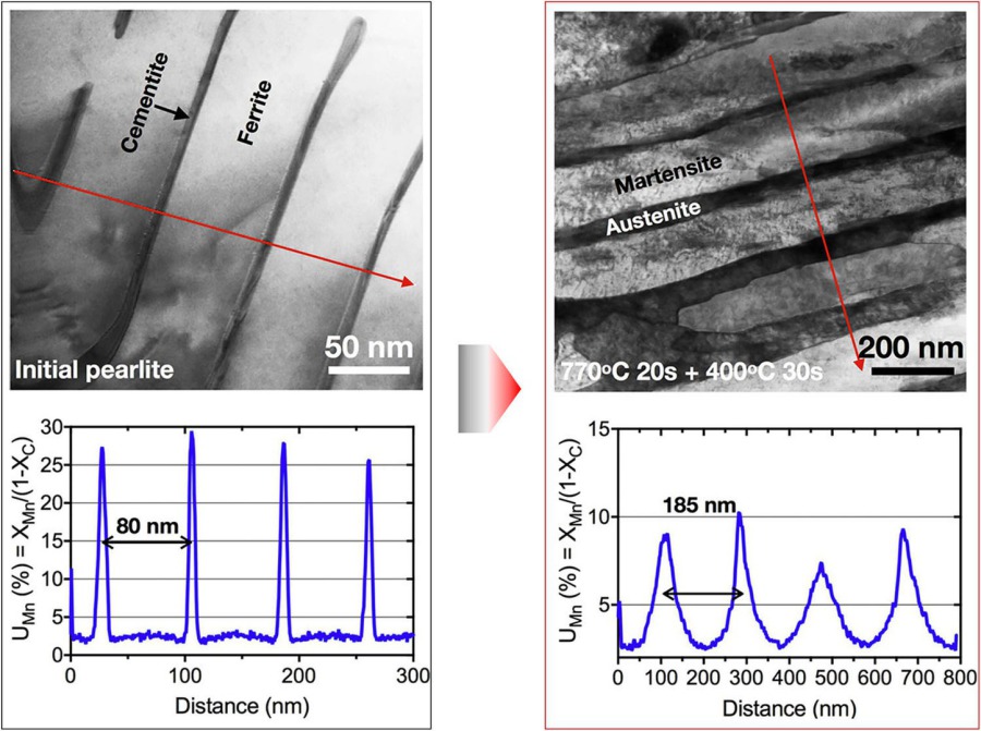 Figure 7. Scanning transmission electron microscopy (STEM) bright field.
The crystallographic orientation relationships that are active during the transformation of austenite to bainite are studied for two TRIP steels by means of Electron BackScatter Diffraction (EBSD). A detailed evaluation of about 360 retained austenite grains and their BCC neighbours was performed. Three relationships were considered, namely Kurdjumov–Sachs, Nishiyama–Wassermann and Pitsch. It was found that the majority of the austenite grains had at least one neighbour that could be related with one of the three orientation relationships. The Kurdjumov–Sachs relationship appeared to be dominant and no strong indication for variant selection could be retrieved from the studied data. It was, however, also demonstrated that some precautions need to be made since a clear distinction bet
ISIJ International 49 (2009) 1601.pdf
PDF-Dokument [1.1 MB]
Deformation of the metastable phase
The defining micromechanism of the class is the TRIP effect: deformation-driven transformation of a soft host phase into a hard martensitic product, accompanied by volume expansion and dislocation accommodation, and producing an exceptionally high strain-hardening rate that delays Considère-type necking (Fig. 8). In ultrafine-grained steels this effect is essential, because below about 1 µm grain size the dislocation-storage mechanisms (forest hardening, dynamical Hall–Petch effect) that normally provide work hardening are suppressed. The strain-hardening capability of the steel correlates strongly with the amount of deformation-induced martensite.
Below T₀, where the chemical free energies of austenite and martensite cross, mechanical work must supply the additional transformation driving force. Stress-induced martensite is assisted by this work alone; strain-induced martensite additionally benefits from the potent nucleation sites that plastic deformation creates. The accepted nucleation picture is the double-shear mechanism of Bogers–Burgers and Olson–Cohen: shears of one-third and three-eighths of the Shockley partial (twinning) shear on {111}γ planes convert fcc austenite to bct martensite, most easily where two shearing systems intersect. In medium-Mn steels, α′-martensite is observed to nucleate at intersections of deformation twins (Fig. 9); micropillar compression shows an orientation dependence consistent with twin-assisted nucleation, and stacking-fault interactions also provide nucleation sites, which explains why α′-martensite formation is largely independent of whether twinning occurs. In submicron-grain alloys, single-shear configurations and local stress concentrations at interfaces have been argued to drive an essentially stress-induced transformation.
ε-Martensite appears in small amounts (a few vol.-%) and behaves as an intermediate stage: the SFE of the austenite is low enough for extensive Shockley-partial slip to form it, but it eventually transforms to α′-martensite and contributes little to strain hardening.
Twinning-induced plasticity operates in parallel. Intercritical partitioning typically brings the austenite SFE into the 15–45 mJ/m² range where mechanical twinning is active; single austenite grains then carry fine twins with spacings of a few tens of nanometres (Fig. 10). Twin boundaries shorten the dislocation mean free path (dynamical Hall–Petch effect) and support back stresses (kinematic hardening). In medium-Mn steels, however, the TWIP contribution to strain hardening is modest: samples tailored with comparable TRIP but different TWIP show only a slight hardening gain from the stronger twin response, much smaller than the gain obtained from a stronger TRIP effect (Fig. 11).
The PLC effect — serrated flow, organized deformation bands, negative strain-rate sensitivity — is a hallmark of these metastable steels (Fig. 12). The classical dynamic-strain-aging picture, in which diffusing carbon locks arrested dislocations, is hard to reconcile with the bulk carbon diffusivity in austenite at room temperature. Modified models invoke Snoek-type rotation of C–vacancy pairs, C–Mn complexes interacting with stacking faults (requiring only single atomic jumps), and pipe diffusion of carbon along dislocation cores. In medium-Mn steels the phenomenon persists even when less than 10 vol.-% metastable austenite remains, which points to a TRIP-aided component: continuously nucleating martensite embryos may trap mobile dislocations, and the martensite may transfer carbon into a mobile, supersaturated state that pins interfacial dislocation sources.
Multiphase composite effects add a further, under-appreciated hardening channel. The plastic mismatch among ferrite, austenite and fresh martensite generates geometrically necessary dislocations (GNDs) at the phase boundaries (Fig. 13). Unlike in dual-phase steels, where the mismatch decays as the hard phase deforms, in medium-Mn steels the mismatch grows with deformation as fresh martensite forms, and the ultrafine grain scale multiplies the phase-boundary area. A steel tailored to be devoid of TRIP, TWIP and DSA still showed good hardening and 14% uniform elongation at a 1.2 GPa yield strength on the strength of the composite effect alone, and a higher degree of strain partitioning nearly doubled the uniform elongation of a comparable steel.
Strain partitioning is the local expression of this composite behaviour. The soft phase yields first and carries most of the strain; in a 0.05C-12Mn-3Al steel, austenite grains accommodate about 20% von Mises strain at a global strain of 10%, against only about 5% in the tempered martensite (Fig. 14). Lamellar morphology, texture memory and the spatial alignment of phase islands relative to the loading axis strongly modulate the localization; austenite lamellae aligned at 45° to the tensile axis experience the largest geometrical shear.
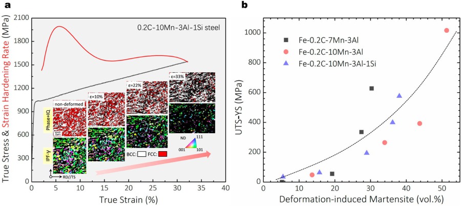 Figure 8. (a) True stress – strain curve, strain-hardening response and the evolution of microstructure upon deformation of an MMnS (0.2C-10Mn-3Al-1Si, in wt-%), intercritically annealed at 750°C for 5 min. The steel possesses an austenite-ferrite.
Scripta Materialia 68 (2013) 343–347-Al-[...]
PDF-Dokument [739.9 KB]
Plastic Yielding of High Strength Metastable Steels
Ultrafine austenite–ferrite medium-Mn steels frequently show discontinuous yielding: a yield-point drop, a stress plateau (yield-point elongation), and Lüders banding (Fig. 15). Two conditions are required: an initially low density of mobile dislocations, and an avalanching increase of mobile dislocations. Three candidate mechanisms have been proposed: the Cottrell–Bilby locking–unlocking of carbon atmospheres; the Johnston–Gilman dislocation-multiplication picture; and an ultrafine-grain mechanism in which boundaries act simultaneously as sinks for grown-in dislocations and as sources of new ones.
The classical carbon-locking explanation runs into difficulties: discontinuous yielding also occurs in steels with more than 50% austenite, where carbon binds only weakly to dislocations; the yield drop is insensitive to the ferrite fraction; and steels with a large fraction of coarse δ-ferrite typically yield continuously. In-situ observation resolves much of the puzzle: the austenite–ferrite phase boundaries — the most prevalent planar defects in these steels — are the preferred dislocation emission sites, and carbon segregated at those boundaries raises the emission barrier, increasing the yield strength by more than 100 MPa. Austenite stability tunes the response: less stable austenite shortens the yield-point elongation because strain-induced martensite inside the Lüders band accelerates band propagation; when stress-induced martensite forms from the onset of loading, discontinuous yielding can be suppressed entirely.
![Figure 9. (a) Schematic illustration showing the chemical free energy change of austenite and martensite as a function of temperature [ 129]. (b) Schematic diagram of the Bogers and Burgers model for austenite-to- α′-martensite transformation [ 134]. The](https://www.dierk-raabe.com/s/cc_images/teaserbox_2498962683.jpg?t=1791716105) Figure 9. (a) Schematic illustration showing the chemical free energy change of austenite and martensite as a function of temperature [ 129]. (b) Schematic diagram of the Bogers and Burgers model for austenite-to- α′-martensite transformation [ 134].
Figure 9. (a) Schematic illustration showing the chemical free energy change of austenite and martensite as a function of temperature [ 129]. (b) Schematic diagram of the Bogers and Burgers model for austenite-to- α′-martensite transformation [ 134].
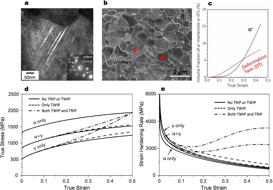 Figure 10. (a) Transmission electron microscopy (TEM) darkfield image with nano-beam diffraction pattern of an austenite grain in a 0.2C-10Mn-3Al-3Si (in wt-%) steel subjected to intercritical annealing at 750°C and subsequent tensile true strain of 15%
Introduction of interlath reverted austenite is an effective method to design ductile lath martensitic steels. The challenge in this concept is that all reverted austenite fi lms have similar mechanical stability, hence, they all undergo transformation-induced plasticity (TRIP) at the same strain level. Here we propose a new thermo-mechanical treatment route to activate the TRIP effect over a broad strain regime and refer to it as ‘spectral TRIP effect’. It aims at spreading the micro-mechanical stability of reverted austenite grains by widening the austenite nucleation barrier in martensite. To validate the proposed thermo-mechanical treatment route, an as-quenched medium-Mn martensitic steel was cold rolled prior to the reversion treatment at 600 C. Microstructure characterization
Acta Materialia 111 (2016) 262 martensit[...]
PDF-Dokument [1.8 MB]
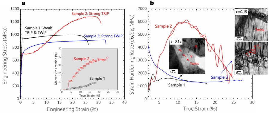 Figure 11. (a) Engineering stress– strain curves and (b) strain-hardening response of different MMnS samples tailored with different degrees of TRIP and TWIP. Sample 1: 0.2C-10Mn-3Al (in wt-%) steel intercritically annealed at 700°C for 5 min;
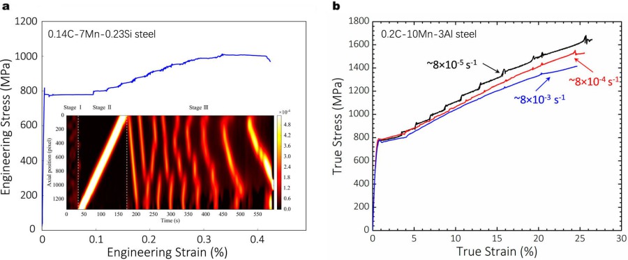 Figure 12. (a) Tensile curve and PLC banding behaviour of a 0.14C-7Mn-0.23Si (in wt-%) steel containing an ultrafine grained austenite-ferrite microstructure. The propagation of PLC bands is shown from the local strain rate map.
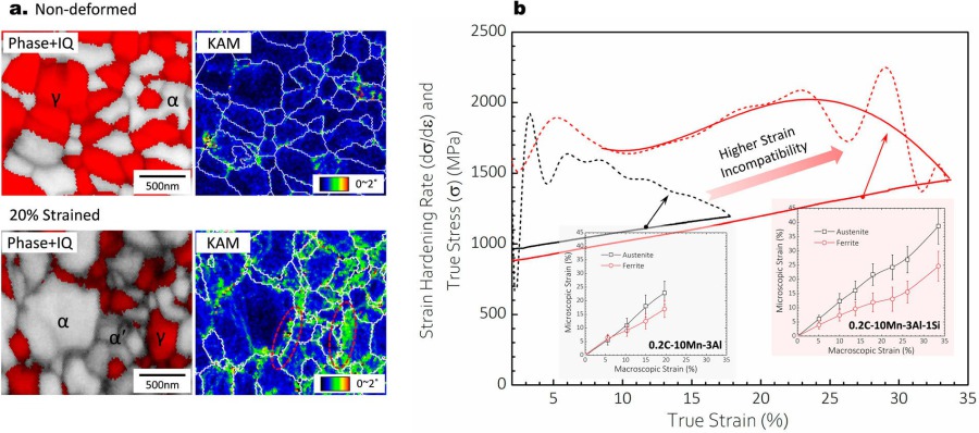 Figure 13. (a) EBSD phase plus image quality (IQ) map and kernel average misorientation (KAM) map of an intercritically annealed MMnS (0.2C-10Mn-3Al-1Si, in wt-%) before and after tensile deformation at 20% strain, showing a higher amount of GNDs.
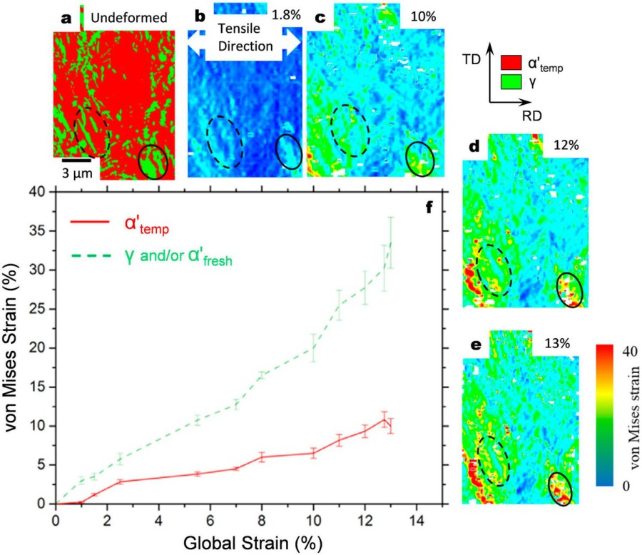 Figure 14. Strain partitioning between austenite ( γR) and/or deformation-induced fresh martensite ( α’fresh) and tempered martensite ( α’temp) in a 0.05C-12Mn-3Al (wt-%) steel subjected to intercritical annealing at 555°C for 12 h. (a) – (e) EBSD phase.
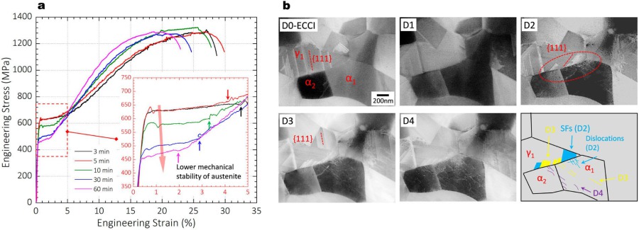 Figure 15. (a) Tensile stress-strain curves of a cold-rolled 0.2C-10.2Mn-2.8Al-1Si (in wt-%) steel intercritically annealed at 800°C for different times (from 3 min to 1 h) to yield different grain size and austenite mechanical stability.
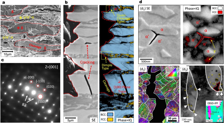 Figure 16. (a) Typical fracture surface and (b) cracking behaviour in a high-Al, high-Si added MMnS (0.2C-10Mn-3Al-3Si, wt-%) containing coarse grained δ-ferrite (the Al and Si contents in δ-ferrite are ∼4 and ∼3.5 wt-%, respectively). (c) SAD.
Damage, fracture and hydrogen embrittlement effects on High Strength Metastable Steels
Most medium-Mn steels fail by the classical ductile route — void nucleation, growth and coalescence — with voids at α–α′, α–carbide, α′–α′ and inclusion interfaces, where elastic–plastic mismatch and dislocation pile-ups concentrate the stress (Fig. 16). High-Al, high-Si grades containing coarse δ-ferrite are the notable exception: cleavage along {100} δ-ferrite planes is promoted by B2/D0₃ ordering and by the large plastic mismatch of the layered microstructure.
Hydrogen embrittlement in the class is microstructure-selective. Three factors govern its expression: the more-than-two-orders-of-magnitude difference in hydrogen diffusivity and solubility between austenite and the ferritic phases; the diversity of phases and interfaces, each with its own trapping and decohesion behaviour; and the austenite→martensite transformation, which resets the local structure and the hydrogen thermodynamics. When hydrogen is trapped at lattice defects inside ferrite, damage proceeds by a HELP-type mechanism with enhanced void nucleation at phase boundaries; when the austenite percolates and hydrogen is trapped at its boundaries and inside it, cracking along the α–γ/α′ interfaces and the prior-austenite grain boundaries by an HEDE-type mechanism dominates. The TRIP effect is generally detrimental to hydrogen resistance: it raises local stresses and drives stress-assisted hydrogen migration, and it converts low-mobility solute hydrogen in austenite into supersaturated, highly mobile hydrogen in martensite. The timing of hydrogen ingress relative to transformation changes the fracture mode — from intergranular plus quasi-cleavage fracture for pre-charged material, to a nanoscale mottled, nano-dimpled surface when hydrogen enters after the transformation.
Deformation-induced martensite plays two opposing roles in damage (Fig. 17). On the one hand, the 3–4% volume expansion on transformation produces compressive fields that suppress void and crack growth and dissipates mechanical work; in fatigue, fresh martensite can also act as a barrier to crack advance. On the other hand, fresh martensite is less tough than ferrite or austenite — above about 0.3 wt% C it is prone to brittle fracture — and its formation increases the plastic mismatch at the interfaces. The design consequence is clear: a sequential, strain-paced transformation of the metastable austenite is preferable to an instantaneous one, because austenite that remains into the necking stage continues to constrain damage growth.
Manganese segregation at prior-austenite grain boundaries is a classical embrittlement pathway (Fig. 18): short anneals at 450 °C produce Mn-rich boundaries and low Charpy toughness, while prolonged annealing allows austenite reversion at the boundaries, which strips the segregation and restores toughness. The thermodynamic origin is the positive excess enthalpy of mixing of Fe–Mn: segregation raises the boundary energy, and cooling quenches the boundary into a higher-energy, crack-prone state.
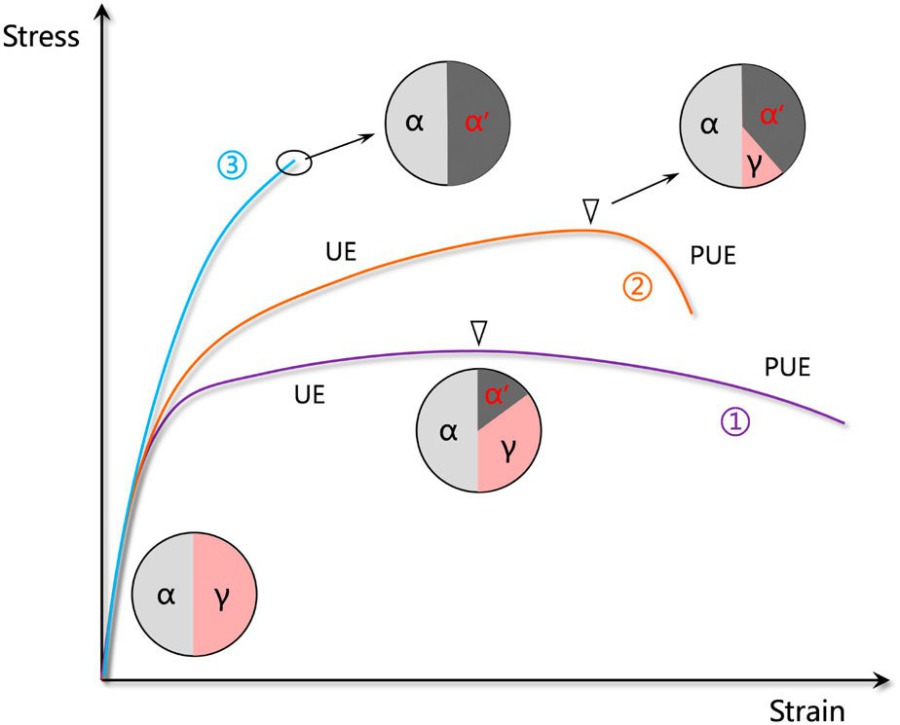 Figure 17. Schematic diagram showing the effects of deformation-induced martensite on the tensile behaviour in three hypothetical MMnS with initially a ferrite-austenite twophase steel and different austenite mechanical stabilities.
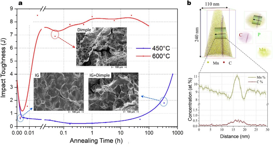 Figure 18. (a) Influence of annealing time on the room temperature Charpy impact toughness of a model Fe-9Mn (in wt-%) alloy, with the fracture surface of some conditions inset. Note that the specimens for the Charpy impact testing.
Processing routes and microstructure design of High Strength Metastable Steels
Intercritical annealing — heating into the austenite–ferrite field, holding to allow solute partitioning, and quenching to retain the high-temperature structure — is the workhorse route for ultrafine austenite–ferrite medium-Mn steels (Fig. 19). Depending on the stored energy in the starting microstructure, the result is either a globular or a laminated (or mixed) morphology: heavy cold rolling drives recrystallization ahead of austenite formation and gives globular grains, while a quenched-martensite starting structure templates the laminated one. The characteristic submicron grain scale most likely reflects Mn solute drag slowing boundary migration; in a 10Mn steel, the grain size grows only slightly from about 650 nm after 3 min to just over 1 µm after 60 min at 800 °C. Annealing temperature governs both strength and hardening: higher temperature gives coarser grains (lower yield strength) and less-enriched, less-stable austenite (stronger initial TRIP). Careful adjustment of the intercritical parameters delivers strength–ductility products of up to about 80 GPa%.
Globular and laminated variants behave differently at the yield point: the globular microstructure shows a more pronounced discontinuous yielding, while the laminated one suppresses it, presumably because dislocation emission is restricted to lamella tips and the avalanching multiplication rate is reduced (Fig. 20). Impact toughness and hydrogen resistance vary with morphology and processing history, and the literature is not fully consistent.
The austenite–martensite combination pairs the strongest phase with the toughest and is considered the ideal third-generation microstructure (Fig. 21). A simple austenitize-and-quench route leaves retained austenite that is unenriched and mechanically unstable — the TRIP effect is exhausted early and ductility is limited. Adding a low-temperature C partitioning treatment (where substitutional diffusion is frozen and carbide formation is suppressed by Si and Al) and/or an Mn enrichment step within the intercritical field stabilizes the austenite, and ductility rises at nearly constant strength (Fig. 22).
Bimodal microstructures — a fine γ+α aggregate plus coarse δ-ferrite or coarse austenite with grains above about 5 µm — appear when Al and Si eliminate the single-phase austenite field, or when C- and Mn-rich compositions retain austenite through casting and rolling (Fig. 23). They tend to yield continuously and match the strength–ductility performance of the ultrafine variants. High-Al/Si grades, however, show poor hot workability: hot torsion at 1000 °C and 1 s⁻¹ fails at a true strain of about 1.0, far below plain-carbon steels, most likely because of the plasticity mismatch and the different dynamic-restoration kinetics of the two phases (Fig. 24).
Measured against the other AHSS families (Fig. 25), medium-Mn steels match or exceed the first-generation grades, reach the level of the second-generation high-Mn steels, and include compositions that combine strengths above 2 GPa with ductilities above 20% — a property spectrum not reached by other bulk-produced steels.
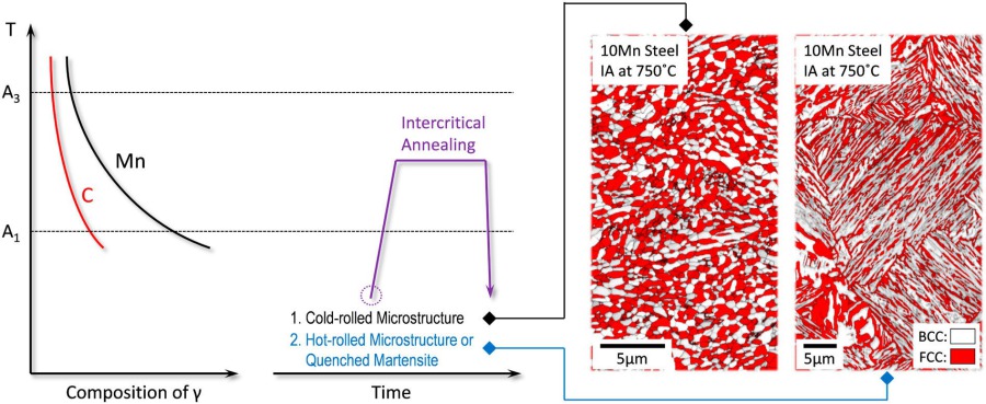 Figure 19. Schematic diagram showing the intercritical annealing process that is normally used to heat treat MMnS and the typical resulting microstructure (the EBSD phase plus IQ maps on the right side are from a 0.2C-10Mn-3Al-1Si (in wt-%) steel.
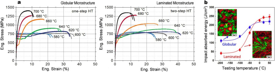 Figure 20. (a) Annealing temperature dependence of the room temperature tensile behaviour of a cold-rolled 0.1C-6.4Mn (in wt- %) steel treated to produce material variants with a globular and laminated microstructure, respectively. The globular microstruc
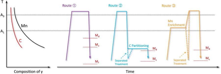 Figure 21. Different processing routes for producing austenite-martensite microstructure in MMnS. Routes 2 and 3 show two typical strategies to enhance the stability of austenite for a more persistent TRIP effect.
![Figure 22. (a) Strength-ductility combinations of MMnS with different types of microstructure (plotted based on published data [1,8,14,16,18,42,47,68,141,151,192,229,233– 245]); (b) Tensile behaviour of a 0.18C-8Mn (wt-%) steel fabricated to have either a](https://www.dierk-raabe.com/s/cc_images/teaserbox_2498962697.jpg?t=1791716477) Figure 22. (a) Strength-ductility combinations of MMnS with different types of microstructure (plotted based on published data [1,8,14,16,18,42,47,68,141,151,192,229,233– 245]); (b) Tensile behaviour of a 0.18C-8Mn (wt-%) steel.
Figure 22. (a) Strength-ductility combinations of MMnS with different types of microstructure (plotted based on published data [1,8,14,16,18,42,47,68,141,151,192,229,233– 245]); (b) Tensile behaviour of a 0.18C-8Mn (wt-%) steel.
Open questions and industrial outlook
Industrial deployment is still at the pre-commercialization stage. Manganese additions above 3 wt% escalate steelmaking costs — the BF/BOF route is complicated by ladle-heat maintenance under large ferromanganese additions, the EAF route requires AOD/VOD stations, and impurity control demands expensive low-carbon ferromanganese or electrolytic Mn. Most processing flows include a batch intercritical anneal that penalizes both cost and property consistency, and continuous annealing is the obvious improvement to pursue. At crash-relevant strain rates (below 10³ s⁻¹), many grades show a negative strain-rate sensitivity that must be eliminated or controlled, and resistance-spot and laser welding suffer from martensite formation and, with Zn coatings, from liquid-metal embrittlement.
The scientific gaps are specific: austenite nucleation from complex starting structures; interface mobility and phase growth; the interaction between recrystallization and reversion; local chemistry and reversion kinetics; the nucleation mechanism of deformation-induced martensite; the quantitative contribution of individual hardening mechanisms; the detailed structure of PLC bands and the underlying DSA; micro-alloying and precipitation; and the role of interface characteristics in damage and hydrogen embrittlement. Reliable microstructure and micromechanical models that can guide composition and microstructure discovery, together with precise local chemistry control within grains and at interfaces, are the most promising paths forward.
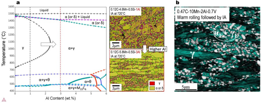 Figure 23. (a) Pseudo-binary equilibrium phase diagram for the 0.12C-5Mn-0.5Si-xAl steel system and typical microstructure of this steel system with different Al additions after cold rolling and intercritical annealing (IA) at 720°C.
 Figure 24. (a) True stress– strain curve of a 0.2C-10Mn-3Al-3Si steel subjected to hot torsion testing at 1000°C and 1 s-1; (b) Microstructure evolution of the same steel during hot compression at the same temperature and strain rate.
![Figure 25. Comparison of tensile properties between MMnS and typical first/second-generation AHSS (plotted based on published data [ 1,8,14,16,18,26,42,47,68,141,151,192,229, 233– 245,253– 262]). HSS: conventional high-strength steels, IF: interstitial-fr](https://www.dierk-raabe.com/s/cc_images/teaserbox_2498962700.jpg?t=1791716572) Figure 25. Comparison of tensile properties between MMnS and typical first/second-generation AHSS (plotted based on published data [ 1,8,14,16,18,26,42,47,68,141,151,192,229, 233– 245,253– 262]). HSS: conventional high-strength steels, IF: interst. free.
Figure 25. Comparison of tensile properties between MMnS and typical first/second-generation AHSS (plotted based on published data [ 1,8,14,16,18,26,42,47,68,141,151,192,229, 233– 245,253– 262]). HSS: conventional high-strength steels, IF: interst. free.
B. Sun, A. Kwiatkowski da Silva, Y. Wu, Y. Ma, H. Chen, C. Scott, D. Ponge, D. Raabe, “Physical metallurgy of medium-Mn advanced high-strength steels”, International Materials Reviews 68(7): 786–824, 2023.
 Druckversion